 |
|||||
| Home | Research | For Teachers | HISTORY Level 1 Level 2 Level 3 |
PRINCIPLES Level 1 Level 2 Level 3 |
CAREER Level 1 Level 2 Level 3 |
| Gallery | Hot Links | What's New! | |||
| Web Administration and Tools | |||||
 |
|||||
| Home | Research | For Teachers | HISTORY Level 1 Level 2 Level 3 |
PRINCIPLES Level 1 Level 2 Level 3 |
CAREER Level 1 Level 2 Level 3 |
| Gallery | Hot Links | What's New! | |||
| Web Administration and Tools | |||||
Flight Instruments - Level 3
![]()
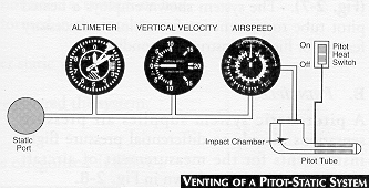
Aircraft constantly encounter atmosphere pressure changes as they climb, descend, accelerate or decelerate. The pitot-static system - sensitive to airspeed, altitude, and rates of altitude change - provides the pressure information displayed on cabin instrumentation.
An outside air temperature sensor must be installed for air data systems.
The airspeed indicator is vented to both pitot and static lines. The airspeed indicator reacts to changes between pitot air and static air. The altimeter and vertical speed indicator, however, require venting to only the static line (see Venting of a Pitot-Static System above). The system shown employs a heated pitot tube to prevent ice formation, a necessary feature for flight in instrument conditions.
B. PRINCIPLES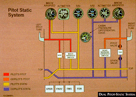
A pitot-static system supplies air pressure sensations directly to differential pressure flight instruments for the measurement of aircraft speed and altitude, as shown in the figure Dual Pitot-Static System.
The pitot tube is a ram air pressure-sensing device usually mounted near the leading edge of the wing and connected to the back of the airspeed indicator case by a tube. Due to its location, the pitot tube is susceptible to foreign matter such as dirt, water and ice. Aircraft used for instrument flight must have a heated pitot tube (see Venting of a Pitot-Static System above) to reduce the possibility of ice obstructing the intake port. Because foreign matter may enter the pitot tube, pilots should carefully inspect the pitot tube and test the heating element before flight.
The static line vents the pitot-static instruments to the outside, or ambient, air pressure through the static port. The static port (See Venting of a Pitot-Static System above, bottom left of diagram) may be located in various places on different types of aircraft and more than one port may be used. Regardless of location, the port is always positioned so the plane of the opening is parallel to the relative air flow. By comparison, the plane of the pitot tube opening is nearly perpendicular to the relative wind. The pressure sensed at the static ports is transferred to the cabin instruments by a tube.
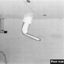 Because moisture condensation within pitot and static lines can
cause erroneous instrument readings, a condensation sump is usually provided in the
system. In addition, some pitot tubes (see Pitot Tube figure,
on the right) have condensation drains. Aircraft used for instrument
flight have an alternate static source because the static line can freeze shut or
the static port can ice over.
Generally, on non-pressurized aircraft, the alternate static source is in the cabin. When used, this source introduces some error in the instruments because the cabin air pressure is lower than outside air pressure due to airflow over the cabin. Airspeeds and altitudes read higher than normal. The vertical airspeed indicator shows a momentary climb as the alternate static source is opened, followed by stabilization and normal readings thereafter.
An outside air temperature sensor is usually a probe mounted to a point along the aircraft's longitudinal axis. The probe compresses the impacting air to zero speed, thus producing and measuring a stagnation temperature. It is shielded to reduce errors from solar radiation and thermal radiation to the relative airflow.
C. INHERENT ERRORS
Varying magnitudes of the errors described here are present within the pitot-static system of any aircraft Full details of a particular system must, therefore, be obtained from Aircraft Flight Manuals.
DENSITY ERROR:
Density error results from variations in atmospheric pressure and temperature. It must normally be determined with the aid of a flight computer (solve for Density and/or True Altitude of True Airspeed). Airspeed, mach indicators and pressure altimeters are affected by density error.
POSITION (INSTALLATION) ERROR:
This error results from incorrect pressure sensations caused by disturbed airflow around the pitot head and/or static vents. It may be either a positive or negative value, which varies according to:
Position error can be sub-divided into two components:
1) FIXED - a set of values common to all aircraft of a given type (which can be determined from correction charts in the appropriate AFM).
2) VARIABLE - a random set of overstresses, deformed skin panels, etc.
Airspeed, mach indicators and pressure altimeters are affected by position error.
COMPRESSIBILITY ERROR:
Compressibility error results from air being compressed in the pitot tube inlet, generally at altitudes above 10,000 feet and calibrated airspeed in excess of 200 knots. It generally produces indicated airspeed readings that are too high.
HYSTERESIS:
Hysteresis results from the imperfect elasticity of aneroid capsules and springs which tend to retain a given shape even though the external forces have changed. It is present during rapid altitude changes and for a short duration thereafter. Hysteresis affects pressure altimeters.
REVERSAL ERROR:
Reversal error results from induced false static pressure sensations caused by large or abrupt pitch changes which give a momentary indication in the opposite direction. It affects pressure altimeters and vertical-speed indicators.
D. SYSTEM MALFUNCTIONS
Various blockages of the pitot-static system can occur. The most common problems are:
Blockage effects may be categorized as follows:
| Instrument | Static Blockage | Pitot Blockage |
| Altimeter | "Freezes" at constant value | n/a |
| Vertical Speed Indicator | "Freezes" at zero | n/a |
| Airspeed Indicator | Under-reads in climb and over-reads in descent | Over-reads in climb and under-reads in descent |
E. PILOT CHECKS
Pilot checks of the pitot-static system relating to specific instruments are covered in the appropriate sections. In general:
F. PITOT-STATIC INSTRUMENTS (Follow link)
G. AIR DATA SYSTEM1. GENERAL: An air data system utilizes the pitot-static system and is found on more sophisticated aircraft. It measures processes, and converts aerodynamic and thermodynamic sensations into electrical signals, synchro outputs, or digital codes.
This system may be used to activate differential pressure flight instruments and to provide information to numerous other aircraft systems. It may incorporate features such as:
2. COMPONENTS: A basic air data system consists of the following components:
a) Sensors. Sensors measure ambient atmosphere surrounding the aircraft. All systems use a pitot tube, static ports, and temperature probe. More complex systems will also make use of an angle of attack sensor;
b) Transducers. Transducers convert the sensed pressure, temperature, and angles to voltages, synchro outputs, or digital pulses. The accuracy and performance of the transducers govern the over-all efficiency of the entire system;
c) Computer. A computer can be designed to perform a multitude of functions, such as:
3. AIR DATA OUTPUTS: A complex air data system can supply a great number of outputs, many of which may be electronic or mechanical variations on the method of presenting one basic parameter of flight (e.g., static pressure).
Some of the common outputs are:
4. INHERENT SYSTEM ERRORS: Central air data computers (CADC) are subject to the following errors:
a) Position Error. This error varies with aircraft type and external configuration. Flight tests are conducted to plot this error on an airspeed, altitude, and configuration curve. The computer manufacturer designs a corrective mechanism or electrical circuit to correct the static-pressure electrical signal being supplied to ail instruments. This results in calibrated airspeed, actual TAS, calibrated altitude, and true Mach indications on the instruments. Because of the individual aircraft type position error, the CADC has to be tailored to that particular aircraft type and is not suitable for use in other types; and
b) Scale Error. Also referred to as instrument error, scale error is associated with a particular set of altitude aneroids and varies with altitude. The individual aneroids of a particular CADC can be plotted for scale error. A corrective camshaft designed to correct the altitude output signal is installed to minimize errors.
NOTE:H. ANGLE-OF-ATTACK SYSTEM
l . GENERAL: The angle of attack is the angle measured between the relative airflow and the wing chord line of an aircraft.
An angle-of-attack system may be used to:
2. SYSTEM COMPONENTS: An angle of attack system consists of the following components:
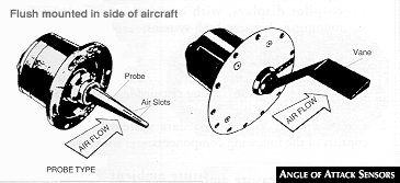 a) Sensors. One or more sensors; protrude
into the relative airflow. There are two common types (see Angle
of Attack Sensors figure to the right):
b) Transducer. Both types of sensors, when aligning with the relative airflow, generate a signal which is passed to the cockpit indicator either directly or through an air data system;
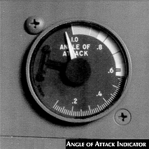 c) Indicators. Various display methods and
cockpit indicators are in use. The Angle of Attack Indicator shown on the
right gives one example. Information may be presented in the form of actual angles, units
or symbols; and
d) Stall-Warning Devices. Most systems incorporate additional devices, such as electrically operated , stick shakers' and/or horns to warn of impending stalls and stick pushers which activate if stall recovery action is not initiated.
WARNING:Send all comments to ![]() aeromaster@eng.fiu.edu
aeromaster@eng.fiu.edu
© 1995-98 ALLSTAR Network. All rights reserved worldwide.
Updated: February 23, 1999