 |
|||||
| Home | Research | For Teachers | HISTORY Level 1 Level 2 Level 3 |
PRINCIPLES Level 1 Level 2 Level 3 |
CAREER Level 1 Level 2 Level 3 |
| Gallery | Hot Links | What's New! | |||
| Web Administration and Tools | |||||
 |
|||||
| Home | Research | For Teachers | HISTORY Level 1 Level 2 Level 3 |
PRINCIPLES Level 1 Level 2 Level 3 |
CAREER Level 1 Level 2 Level 3 |
| Gallery | Hot Links | What's New! | |||
| Web Administration and Tools | |||||
Flight Instruments - Level 3
PITOT-STATIC INSTRUMENTS![]()
 1. AIRSPEED INDICATOR AND V SPEEDS: The pilot can
receive a great deal of information from the airspeed indicator. Regardless of temperature
or altitude, the airspeed indication is the same for specific aircraft performance. For
example, if the aircraft has an indicated stalling speed of 62 knots (kts) at sea level,
it will stall at the same indicated airspeed at 5,000 ft (all other factors being equal).
Vented to both pitot and static lines, the airspeed indicator reacts to any change between
ram (dynamic) air pressure and static (passive) air pressure. The
greater the differential between these two readings, the greater the airspeed.
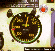
The instrument (see Types of Airspeed Indicator figure, to the right) contains a single pressure diaphragm connected to the pitot line; the airtight case surrounding the diaphragm is vented to the static line. Pitot ram air expands the diaphragm proportional to speed, and diaphragm movement is transferred to the needle on the instrument face by means of a mechanical linkage.
BASIC AIRCRAFT SPEEDSIndicated airspeed (IAS) reflects true airspeed (TAS) only when ICAO standard atmospheric conditions prevail i.e., temperature 15°C, and pressure of 29.92 in. Hg at sea level. Calibrated airspeed (CAS) corrects the indicated airspeed for errors primarily resulting from the position of the static source and, to a much lesser degree, from pitot tube locations. The major errors are mainly due to differences in airflow over the static port at varying angles of attack. The errors usually are greatest in the low and high-speed ranges and smallest in normal operating speeds. Calibrated airspeed tables correct the whole range of indicated airspeed for these installation errors and can be found in the aircraft flight manual.
The flight computer calculates the TAS by converting the IAS under actual conditions to a standard temperature and pressure. This conversion is necessary because the pitot-static system operates accurately only at the standard conditions mentioned above.
By using a flight computer, the pilot can calculate the TAS by applying the actual outside air temperature to the pressure altitude. Some airspeed indicators incorporate a TAS computer (See the Color Markings on Instruments figure, below right)enabling the pilot to read TAS directly from the outermost scale on the face of the indicator.
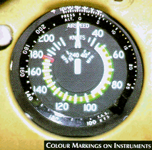
The face of the airspeed indicator on General Aviation (GA) aircraft usually shows both statute and nautical miles per hour (see Color Markings on Instruments figure, on the right). It also has colored arcs to show important speed limits and operating speed limits and operating ranges, along with various V speeds relating to the color markings or airspeed bugs on the instrument.
Pilots should remember that all of these markings and airspeed limitations on the instrument are expressed in calibrated airspeeds.
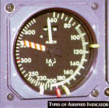 The white arc on the
airspeed indicator designates the flap operating range. The green arc shows the
normal operating range, and the yellow (caution) arc signifies the smooth air
cruising range. A red line usually indicates the Vne (never exceed) speed. Pilots should
never use the caution range during turbulent atmospheric conditions. The aircraft manual
defines additional V speeds not shown on the airspeed indicator.
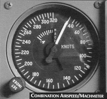
Some airspeed indicators incorporate a Machmeter for high-speed operations. It provides a continuous indication of the ratio of an air crafts airspeed to the local speed of sound. (see Combination Airspeed/Machmeter figure, above left). Some airspeed indicators also incorporate a maximum allowable airspeed pointer, which continuously displays the maximum allowable airspeed for a particular aircraft (see Types of Airspeed Indicator figure, above right).
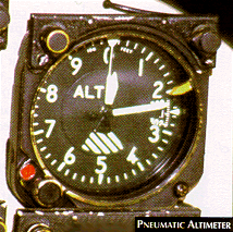 2. ALTIMETER: The altimeter senses the normal
decrease in air pressure that accompanies an increase in altitude. The airtight instrument
case is vented to the static port. With an increase in altitude, the air pressure within
the case decreases and a sealed aneroid barometer (bellows) within the case expands. The
barometer movement is transferred to the indicator (see Pneumatic
Altimeter figure, on the right), calibrated in feet and
displayed with two or three pointers. Different types of indicators display indicated
altitude in a variety of ways.
Generally, this instrument responds immediately to altitude changes. During climbs and descents, however, the altimeter may lag behind the air crafts actual altitude. For this reason, some lead is necessary when leveling off to compensate for this characteristic. A simple rule of thumb is to lead the desired level-off altitude by 10% of the vertical velocity.
An indication of feet above sea level is possible only if the current altimeter setting is in the window on the face of the instrument.
Caution should be exercised when reading the thousands of feet pointer or indicator of the altimeter as it can often be misleading.
ALTIMETER SETTING WINDOWThe altimeter is a calibration unit because the aneroid barometer cannot differentiate between actual altitude changes and changes in the barometric pressure of the air mass itself. The altimeter setting window (See the Pneumatic Altimeter figure above right) allows the pilot to set the current altimeter setting on a small scale, calibrated in inches of mercury. The indicator responds only to altitude changes, as long as the altimeter setting is accurate and the pilot "updates" the current setting as new reports come in.
An aircraft altimeter which has the current altimeter setting applied to the subscale should not have an error of more than ± 50 ft when compared on the ground against a known aerodrome/runway elevation. Altimeter initial certification requirements are ± 20 ft. at sea level increasing to ± 230 ft. at 40,000 ft. If the error is more than ± 50 ft. the accuracy of the altimeter is questionable and the problem should be investigated prior to flight. Investigation could include updating the altimeter setting, comparing with other altimeters, adjusting for height of location of altimeter and many other possibilities.
ALTITUDE DEFINITIONS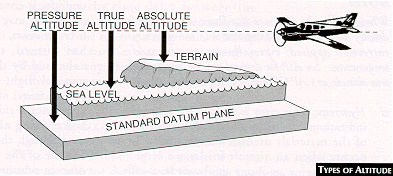
a) Position Error: In some installations, position error can be of considerable magnitude.
b) Scale Error: Commonly referred to as instrument error, scale error is caused by the aneroids not assuming the precise size designed for a particular pressure difference. This error is irregular throughout the range of the instrument (it might be -30 feet at 1,000 feet and +50 feet at 10,000 feet). The tolerances for this error became larger as the measured altitude is increased.
c) Mechanical Error: Mechanical error is caused by misalignment or slippage in the gears and linkage connecting the aneroids to the display, or in the shaft of the barosetting knob.
d) Density Error.- ICAO Standard Atmosphere conditions seldom prevail, and the resulting density error is only partially offset by the diligent application of correct altimeter settings (station or standard pressure). It can generally be disregarded for Air Traffic Control purposes, since all pressure altimeters in close proximity react in the same way, and vertical separation is maintained.
e) Hysteresis: This error is a lag in the altitude indications caused by the elastic properties of the materials used in the aneroids. It occurs when an aircraft initiates a large, rapid altitude change or an abrupt level-off from a rapid climb or descent. It takes a period of time for the aneroids to catch up with the new pressure environment; hence, a lag in indications. This error has been significantly reduced in modern altimeters and is considered negligible at normal rates of descent for jet aircraft.
f) Reversal Error: During abrupt or rapid attitude changes, reversal error occurs; it is only momentary in duration.
ALTIMETERS ARE SUBJECT TO THE FOLLOWING EFFECTS:a) Effect of Mountains: Winds which are deflected around large single mountain peaks or through the valleys of mountain ranges tend to increase speed, which results in a local decrease in pressure (Bernoulli's Principle). A pressure altimeter within such an air flow would be subject to an increased error in altitude indication by reason of this decrease in pressure. This error will be present until the airflow returns to "normal" speed some distance downwind of the mountain or mountain range. Winds blowing over a mountain range at speeds in excess of about 50 knots and in a direction perpendicular (within 30 degrees) to the main axis of the mountain range often create the phenomena known as "Mountain or Standing Wave".
b) Downdraft and Turbulence.- Downdrafts are most severe near a mountain and at about the same height as the summit. These downdrafts may reach an intensity of 83 feet/second (5,000 feet/minute) to the leeward side of high mountain ranges such as the Rockies. Although Mountain Waves often generate severe turbulence at times, flight through waves may be remarkably "smooth" even when the intensity of downdrafts and updrafts is considerable. As these smooth conditions may occur at night, or when an overcast exists, or when no distinctive cloud has formed, the danger to aircraft is enhanced by the lack of warning of the unusual flight conditions. Consider the circumstances of an aircraft flying parallel to a mountain ridge on the downwind side and entering a smooth, intense downdraft - although the aircraft starts descending because of the downdraft due to the local drop in pressure associated with the wave, both the rate of climb indicator and the altimeter will initially not indicate a descent; in fact, both instruments may actually indicate a "climb" for part of this descent.
c) Pressure Drop: The "drop" in pressure associated with the increase in wind speeds extends throughout the Mountain Wave, that is, downwind and to "heights" well above the mountains. Isolating the altimeter error due solely to the Mountain Wave, or from error due to non-standard temperatures, would be of little value to a pilot. Of main importance is that Mountain Waves and non-standard temperature, in combination, may result in AN ALTIMETER OVERREADING BY AS MUCH AS 3,000 FEET.
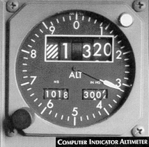 COMPUTER INDICATOR
Operation of the computer-indicator is automatic with the application of AC power (see Computer Indicator Altimeter figure on the right). A failure warning flag with the word OFF, located in the face of the instrument, gives an OFF indication to the pilot in case of a power interruption or a component fault. If the OFF indication is caused by power failure, the flag will disappear when the power is restored. If the OFF indication is the result of a component failure, the flag will remain unchanged.
SERVO/PNEUMATIC ALTIMETER
Operation of the servo-pneumatic system is determined by the pilot's mode selection. The instrument is energized for operation in the primary servo mode at take-off or in flight by moving the RESET/STBY switch to the RESET position. In the event that the instrument has changed to the standby mode of operation as a result of a fault in the system, the pilot may reset the altimeter to the servo mode by selecting the RESET position. Under "no go" conditions, the system will immediately refer to the standby mode when the reset switch is released. Any of the following conditions will cause the failure-monitor circuit to de-energize the relay, and the STBY warning flag to appear:
Before flight, the following checks should be performed (or as indicated in the AFM):
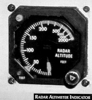 3. RADAR ALTIMETER: A radar altimeter (sometimes
called a radio altimeter) indicates absolute altitude above the surface of the
earth. A typical radar altimeter generally has a single pointer sweeping a
logarithmic scale, which expands toward 0 (see Radar Altimeter
Indicator figure on the right). It usually features a minimum
altitude marker, which can be set to a desired altitude above ground and which generates a
visual and/or audio warning when the aircraft descends to, or is below, the preset value.
The radar altimeter may also feature a warning flag, which is actuated whenever large
pitch or bank angles introduce a slant range inaccuracy.
The equipment determines height by measuring the time delay between the transmission of downward-directed radio waves and the reception of ground-reflected signals. Inaccuracies may be present during flight over any medium into which radio waves can penetrate (ice, deep snow), or over rapidly changing terrain.
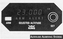 4. ALTITUDE ALERTING SYSTEM: An altitude alerting
system works with altimeter data. The desired level-off altitude is set on the altitude
selector during a climb or descent.
The pilot is alerted by aural or visual signals upon approaching the prescribed altitude in sufficient time to establish level flight at that preselected altitude (usually 1,000 ft. above or below the selected altitude). A typical altitude alerting system is shown in the Altitude Alerting System figure on the right.
5. VERTICAL SPEED INDICATOR: The Vertical Speed Indicator (VSI) displays the vertical component of an aircraft's flight path. It measures the rate of change of static pressure in terms of feet per minute of climb or descent. The VSI automatically compensates for changes in atmospheric density.
The VSI is in a sealed case connected to the static line through a calibrated leak (restricted diffuser). Inside the case, a diaphragm attached to the pointer by a system of linkages is vented to the static line without restrictions.
 As the aircraft climbs, the diaphragm contracts and the pressure
drops faster than the case pressure can escape through the restrictor, resulting in climb
indications; the reverse is true during descent. If level flight is resumed, pressure
equalizes in the case and diaphragm within six to nine seconds and the pointer returns to
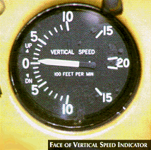
zero rate of climb. The vertical speed indicator has 100-ft calibrations with numbers
every 500 ft (see Face of Vertical Speed Indicator
figure on the right).
The vertical speed indicator has two separate functions. First, it operates as a trend instrument because it shows deviations from level flight before the altimeter registers any signs. There is no lag in this function. Second, it serves as a rate indicator. The calibrated leak prevents the pressure differential between the case and the bellows from equalizing immediately, causing an inherent lag. When the aircraft starts a climb or descent, it takes a few seconds for a pressure differential to develop between the same areas and indicate a rate of movement. The same is true when leveling off.
In summary, when the aircraft begins a climb or descent, the instrument immediately displays the change in pitch; however, the pilot must wait for six to nine seconds for an accurate indication of the rate of climb or descent. Nonetheless, the vertical speed indicator is valuable in sensing deviations from a selected altitude or establishing a constant rate of climb or descent.
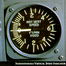 6. INSTANTANEOUS VERTICAL SPEED INDICATOR: An
instantaneous vertical speed indicator (IVSI) displays vertical speed information with
essentially zero, time lag. A single pointer indicates rate of altitude change against a
fixed circular scale much the same as a vertical speed indicator (see
Instantaneous Vertical Speed Indicator figure on the right).
This instrument is similar in operation to a vertical speed indicator, except that accelerometers have been added to the linkage between the capsule and the pointers. These sense accelerations of vertical velocity and provide appropriate motion to the pointer before any static pressure differential has been established.
Send all comments to ![]() aeromaster@eng.fiu.edu
aeromaster@eng.fiu.edu
© 1995-98 ALLSTAR Network. All rights reserved worldwide.
Updated: February 23, 1999