 |
|||||
| Home | Research | For Teachers | HISTORY Level 1 Level 2 Level 3 |
PRINCIPLES Level 1 Level 2 Level 3 |
CAREER Level 1 Level 2 Level 3 |
| Gallery | Hot Links | What's New! | |||
| Web Administration and Tools | |||||
 |
|||||
| Home | Research | For Teachers | HISTORY Level 1 Level 2 Level 3 |
PRINCIPLES Level 1 Level 2 Level 3 |
CAREER Level 1 Level 2 Level 3 |
| Gallery | Hot Links | What's New! | |||
| Web Administration and Tools | |||||
Aircraft Propulsion - Level 3
![]()
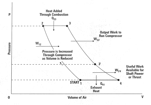
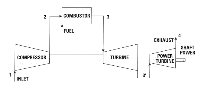
A cycle describes what happens to air as it passes into, through, and out of the gas turbine. The cycle usually describes the relationship between the space occupied by the air in the system (called volume, V) and the pressure (P) it is under. The Brayton cycle (1876), shown in graphic form in Fig. 4a as a pressure-volume diagram, is a representation of the properties of a fixed amount of air as it passes through a gas turbine in operation. These same points are also shown in the engine schematic in Fig. 4b.
Air is compressed from point 1 to point 2. This increases the pressure as the volume of space occupied by the air is reduced. The air is then heated at constant pressure from 2 to 3 in Fig. 4. This heat is added by injecting fuel into the combustor and igniting it on a continuous basis. The hot compressed air at point 3 is then allowed to expand (from point 3 to 4), reducing the pressure and temperature and increasing its volume. In the engine in Fig. 4b, this represents flow through the turbine to point 3' and then flow through the power turbine to point 4 to turn a shaft or a ship's propeller. In an aircraft jet engine, the flow from point 3' to 4 is through the exit nozzle to produce thrust. The "useful work" in Fig. 4a is indicated by the curve 3'- 4. This is the energy available to cause output shaft power for a land-based gas turbine, or thrust for a jet aircraft. The Brayton cycle is completed in Fig. 4 by a process in which the volume of the air is decreased (temperature decrease) as heat is absorbed into the atmosphere.

Figure 4a. Brayton cycle pressure-volume diagram for a unit mass of working fluid
(e.g., air), showing work (W) and heat (Q) inputs and outputs.

Figure 4b. Gas turbine schematic showing relative points from the
Brayton Cycle diagram.
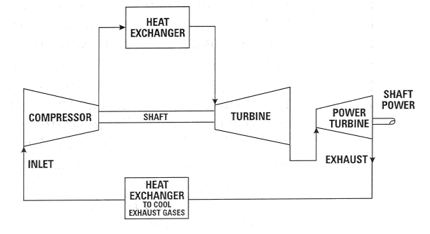
Most gas turbines operate in an open cycle mode where, for instance, air is taken in from the atmosphere (point 1 in Figs. 4a and 4b) and discharged back into the atmosphere (point 4), with the hot air being cooled naturally after it exits the engine. In a closed cycle gas turbine facility, such as a land-based gas turbine facility, the working fluid (air or other gas) is continuously recycled by cooling the exhaust air (point 4) through a heat exchanger (shown schematically in Fig. 5) and directing it back to the compressor inlet (point 1).

Figure 5. Closed Cycle System.
Because of its confined, fixed amount of gas, the closed cycle gas turbine is not an internal combustion engine. In the closed cycle system, combustion cannot be sustained and the normal combustor is replaced with a second heat exchanger to heat the compressed air before it enters the turbine. The heat is supplied by an external source such as a nuclear reactor, the fluidized bed of a coal combustion process, or some other heat source. Closed cycle systems using gas turbines have been proposed for missions to Mars and other long term space applications.
A gas turbine that is configured and operated to closely follow the Brayton cycle (Fig. 4) is called a simple cycle gas turbine. Most aircraft gas turbines operate in a simple cycle configuration since attention must be paid to engine weight and frontal area. However, in land or marine applications, additional equipment can be added to the simple cycle gas turbine, leading to increases in efficiency and/or the output of a unit. One such modification is reheating.
Reheating occurs in the turbine and is a way to increase turbine work without
changing compressor work or melting the materials from which the turbine is constructed.
Reheat in a jet engine is accomplished by adding an afterburner at the turbine exhaust,
thereby increasing thrust, at the expense of a greatly increased fuel consumption rate.
More information on land and marine applications of the gas turbine can be found in the original article, Introduction to Gas Turbines for Non-Engineers, by Lee S.Langston, University of Connecticut and George Opdyke, Jr., Dykewood Enterprises, in the ASME International Gas Turbine Institute's "Global Gas Turbine News", Volume 37, No.2, 1997, from which this section on aircraft gas turbines has been extracted with permission.
Send all comments to ![]() aeromaster@eng.fiu.edu
aeromaster@eng.fiu.edu
© 1995-98 ALLSTAR Network. All rights reserved worldwide.
| Funded in part by | From ASME The International Gas Turbine Institute |
Updated: February 23, 1999