 |
|||||
| Home | Research | For Teachers | HISTORY Level 1 Level 2 Level 3 |
PRINCIPLES Level 1 Level 2 Level 3 |
CAREER Level 1 Level 2 Level 3 |
| Gallery | Hot Links | What's New! | |||
| Web Administration and Tools | |||||
 |
|||||
| Home | Research | For Teachers | HISTORY Level 1 Level 2 Level 3 |
PRINCIPLES Level 1 Level 2 Level 3 |
CAREER Level 1 Level 2 Level 3 |
| Gallery | Hot Links | What's New! | |||
| Web Administration and Tools | |||||
![]()
| Netscape users: Please be advised that this page contains JAVA script to show the animations. In order to view the animations effectively, please move your mouse over the "hot" words embedded in the text but do NOT click on them, otherwise it will take you back to our homepage. If that happens, use the "BACK" button to return to this page. |
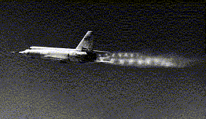
Did you ever wonder why a diamond pattern forms in the exhaust gases when a rocket lifts off or when high performance aircraft like the SR-71 Blackbird takes-off or the Bell X-2 was dropped from the belly of her mother ship? Did you ever wonder why the exhaust gases of the shuttle billow out at high altitude and not at low altitude? Well here is an explanation.


As the rocket lifts off the pad, you can see several things happen to the rocket nozzle's exhaust plume. First, if you look closely as the engines initially fire up to reach lift-off thrust conditions, a diamond pattern can be seen to exist at the exit of the rocket nozzle. Then as the rocket goes higher and higher, the rocket's exhaust plume seems to become wider and wider. These two effects occur because of the design of the rocket nozzle.

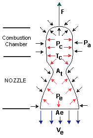
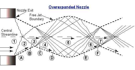
The rocket's nozzle (see diagram below) is designed to be efficient at altitudes above sea level, and, at engine start, the flow is overexpanded, that is, the exhaust gas pressure, pe, is higher than the supersonic isentropic exit pressure but lower than the ambient pressure, pa. This causes an oblique shock to form at the exit plane (A) of the nozzle. To reach ambient pressure, the gases undergo compression as they move away from the nozzle exit and pass through the oblique shock wave standing at the exit plane. The flow that has passed through the shock wave will be turned towards the center line (2). At the same time, the oblique shock wave, directed toward the center line of the nozzle, cannot penetrate the center plane since the center plane acts like a streamline. This causes the oblique shock wave to be reflected outward (B) from the center plane. The gas flow goes through this reflected shock and is further compressed but the flow is now turned parallel (3) to the centerline. This causes the pressure of the exhaust gases to increase above the ambient pressure.

The reflected shock wave (see diagram below) now hits the free jet boundary called a contact discontinuity (or the boundary where the outer edge of the gas flow meets the free stream air). Pressure is the same across this boundary and so is the direction of the flow. Since the flow is at a higher pressure than ambient pressure, the pressure must reduce. Thus, at the reflected shock wave-contact discontinuity intersection, expansion waves of the Prandtl-Meyer (P-M) type are set up (C) to reduce the pressure to pa. These expansion waves are directed towards the centerline of the nozzle. The gas flow passing through the Prandtl-Meyer expansion waves turn away from the centerline (4). The Prandtl-Meyer expansion waves in turn reflect from the center plane towards the contact discontinuity (D). The gas flow passing through the reflected Prandtl-Meyer waves is now turned back parallel to the centerline but undergoes a further reduction of pressure.

The reflected Prandtl-Meyer waves (see diagram directly above) now meet the contact discontinuity and reflect from the contact discontinuity towards the centerline as Prandtl-Meyer compression waves (E). This allows the gas flow to pass through the Prandtl-Meyer compression waves and increase its pressure to ambient pressure, but passage through the compression waves turns the flow back towards the centerline (6). The Prandtl-Meyer compression waves now reflect from the center plane as compression waves (F) further increasing the pressure above ambient, but turning the flow parallel to the nozzle centerline (7). The flow process is now back to when the flow had just passed through the reflected shock wave (B), i.e., the flow pressure is above ambient and the flow is parallel to the centerline (3). This process of expansion-compression wave formation begins anew and continues until the pressure of the gases are the same as the ambient pressure and the flow is parallel to the centerline of the nozzle. These expansion and compression waves that interact with each other, leads to the diamond patterns seen. Ideally, this process would continue without end; but a turbulent shear layer created by the large velocity differences across the contact discontinuity will dissipate the wave patterns (see the diamond pattern for the SR-71 Blackbird at the beginning of this section).
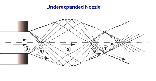
At very high altitudes where the ambient pressure is less than the exhaust pressure of the gases, the flow is underexpanded (see diagram below) -- the exhaust gases are exiting the nozzle at pressures below the supersonic isentropic exit pressure which is also the ambient pressure. Thus, the flow (3 below) is at the same condition (pexhaust > pa) as the flow was after it passed through the reflected oblique shock wave when the rocket was at sea level (see above, A). To reach ambient pressure, the exhaust gases expand via Prandtl-Meyer expansion waves (waves between sections 3 and 4, below). This expansion occurs by the gases turning away from the centerline of the rocket engine (4). Therefore, the exhaust plume is seen to billow out from the rocket nozzle. The rest of the process (4-5-6-7, below) is the same as the 4-D-5-E-6-F-7 process explained above for the overexpanded nozzle.

TO THE ROCKET CONTROLS PAGE - SECTION 4
Send all comments to ![]() aeromaster@eng.fiu.edu
aeromaster@eng.fiu.edu
© 1995-98 ALLSTAR Network. All rights reserved worldwide.
Updated: February 23, 1999