 |
|||||
| Home | Research | For Teachers | HISTORY Level 1 Level 2 Level 3 |
PRINCIPLES Level 1 Level 2 Level 3 |
CAREER Level 1 Level 2 Level 3 |
| Gallery | Hot Links | What's New! | |||
| Web Administration and Tools | |||||
|
|||||
| Home | Research | For Teachers | HISTORY Level 1 Level 2 Level 3 |
PRINCIPLES Level 1 Level 2 Level 3 |
CAREER Level 1 Level 2 Level 3 |
| Gallery | Hot Links | What's New! | |||
| Web Administration and Tools | |||||
Radio Detection And Ranging
Radar is an acronym which stands for Radio Detection and Ranging. This is the method
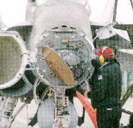
by which we can detect aircraft in our area. At the heart of the F-15E is the APG-70
radar. In the air-to-air mode, the APG-70 can provide range, altitude, airspeed, and other
information on aircraft at ranges exceeding 100 miles. The APG-70 can also produce near
photo quality images of the ground by using synthetic aperture radar (SAR) technology. SAR
imaging is made possible by enhancing the radar returns received from the process known as
the Doppler Shift.
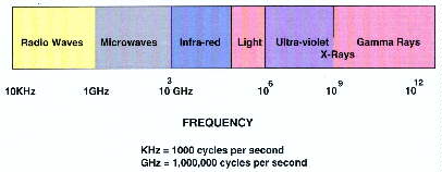
Radar is part of the electromagnetic spectrum, a fundamental element of the universe we
live in. At the low end of the spectrum are the Very Low Frequencies (VLF) used for long
range communications. Next, are radio waves followed by microwaves (Radar). Higher
frequencies above radar include the infrared frequencies and the very small range of
wavelengths commonly called light (the section of the electromagnetic spectrum which
allows us to see with our eyes). Above light are the frequencies of ultra-violet, X-Ray,
and finally Gamma-rays.
Radar 101
The two basic types of radar are PULSE and CONTINUOUS WAVE.
The PULSE radar is the more conventional radar, which transmits a burst of radar energy
and then waits for the energy (or echo) to be reflected back to the antenna. After a
specific period of time (depending on how far the radar is searching) another pulse will
be sent followed by another listening period. Since radar waves travel at the speed of
light, range from the return can be calculated.
CONTINUOUS WAVE (CW) radars transmit a constant beam of radar energy. When a CW radar
illuminates a moving object (such as an aircraft or a car) the radar wave returns to a
separate antenna with a frequency that is slightly higher (if the object is moving toward
the radar) or lower than the frequency of the original radar energy. By measuring this
change of the Doppler Shift the speed of the object can be
determined. In a pure CW radar, the range to the object cannot be determined. However,
human ingenuity has discovered that by manipulating the frequency of the radar over time,
the object's range can be calculated from a CW radar.
Since PULSE and CW radars have their own advantages and disadvantages, many advanced
radars like the APG-70 are "Pulse-Doppler" radars -- combining the principles of
both radars allowing greater capability.
BASIC RADAR TERMS
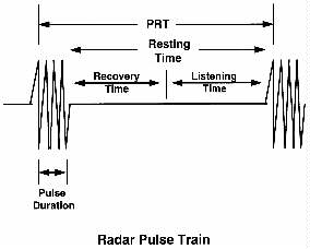
The following provides the basic definitions of the characteristics of a PULSE radar wave:
Pulse Duration (PD): The time a radar set is transmitting radio frequency
(RF) energy. It is also referred to as pulse width (PW). Pulse duration is measured in
millionths of a second or microseconds (usec).
Pulse Recurrence Time (PRT): This is the time required to complete one
transmission cycle. It is the time from the beginning of one radar pulse to the beginning
of the next. It is the reciprocal of our next term, Pulse Recurrence Frequency (PRF).
This term represents the period for one transmission cycle.
Pulse Recurrence Frequency (PRF): The PRF equals the number of pulses per
second the radar transmits. If you want the radar to look at long ranges, a low PRF is
required (this allows time for the radar energy to be reflected by the target and to
return to the antenna before the next pulse is transmitted). For shorter ranges, a higher
PRF can be used. Of course, if you want both then your radar needs the ability to
alternate the PRF.
The relationship between PRF and PRT is
PRF = 1/PRT
Rest Time: This is the time between the end of one transmission and the
start of the next. It is measured in usec. The rest time is divided into two sections,
Recovery Time and Listening Time.
Recovery Time (RT): Represents the time immediately following the
transmission of RF energy. Due to the laws of physics, the radar is unable to process the
echoes of radar returns during this time.
Listening Time (LT): Listening time is the part of the Rest Time that the
radar can receive and process the echoes of radar returns. It is measured is usec.
Beamwidth (BW): Determines the accuracy of the azimuth and elevation
angles. It is measured in degrees. For example, a weather radar usually sweeps 360
degrees (an entire circle). The accuracy of the radar (or how closely it can determine the
location of a thunderstorm, rain showers, etc.) is based on the beamwidth of the radar and
the range to the weather system. The accuracy at a given range can be determined by
multiplying the beamwidth and the range, then dividing by 60. Thus, if a weather radar has
a beamwidth of 1 degree and the thunderstorm is 20 miles from the radar, the formula gives
us:
1 degree x 20 miles / 60 = 1/3 of a mile
In this example, the radar can accurately plot the thunderstorm to within 1/3 of a mile of
its actual position. As range increases, the 1 degree beamwidth will expand to cover a
larger section of the sky and the azimuth resolution will decrease. For example, if the
storm is 60 miles away, then the azimuth resolution would be:
1 degree x 60 miles / 60 = 1 mile
For an air-to-air radar with a 1 degree beamwidth, this rule implies that the radar could
not distinguish between two separate aircraft at a range of 60 miles UNLESS the aircraft
were separated by greater than 1 mile (if they are closer together than 1 mile, they will
appear as a single target).
NOTE: This geometric equation is commonly referred to as the "1 in
60" rule and is used for many applications throughout aviation. An easy example of
how the 1 in 60 rule works is to drive a car at a heading of 090 (90 degrees). Starting
from the same point, another car drives on a heading of 089 (89 degrees). When both cars
have traveled 30 miles, they will be 1/2 mile separation between the cars (1 degree
separation x 30 mile range/60). After driving 60 miles there will be 1 mile of
separation (1 degree x 60 mile range/60), at 120 miles -- 2 miles of separation between
the vehicles. If their headings were 5 degrees different (090 and 085), then the
separation at 60 miles would be
5 degrees separation x 60 miles range / 60 = 5 miles
When performing math in a cockpit, it needs to be simple! The 1 in 60 rule allows aircrews
to mentally make adjustments for time and navigation very quickly and accurately.
How does a radar determine range?
As stated previously, radar waves travel at the speed of light or about 162,000 nautical
miles per second (approximately 186,000 statue miles per second). This can be translated
into 6.2 usec per nautical mile. (1 / 162,000 miles per second = 1 nautical mile in
0.0000062 or 6.2 usec) To measure distance from the radar to the target, we need to double
this value (since the radar wave must travel to the target and then return to the
antenna). This provides us with the formula of:
Target Range (NM) = Target time (usec) / 12.4 (usec)
Example: An F-15E radar receives a radar echo from a target 124 usec after it was
transmitted. What is the range to the target?
Solution: Target time = 124 usec. Placing this value in the formula gives us 124 usec/12.4
usec = 10 nautical miles.
Synthetic Aperture Radar (SAR)
The SAR mode of the APG-70 provides the Strike Eagle aircrews with a capability unmatched
by any other fighter. SAR technology provides a resolution (or the ability to see closely
spaced objects clearly as opposed to one large return) over 100 times greater than a
conventional radar.
SAR technology starts with the antenna. The larger the antenna -- the better the
resolution. Since fighters are limited in size, one way around this is to have the radar
take several "snapshots" of an area on the ground. This simulates a much larger
antenna (it also requires a high powered computer). Since the F-15E is flying at around 9
miles per minute, the range and azimuth to the target constantly changes. Range is
calculated conventionally (addressed above). The azimuth is measured by the Doppler Shift. By taking the Doppler shifts from numerous radar
returns of the same area, the computer is able to provide the phenomenal resolution
required for a near photo quality presentation.
Photo of Airfield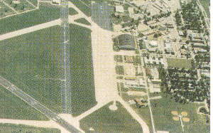
SAR Image of Airfield
Send all comments to ![]() aeromaster@eng.fiu.edu
aeromaster@eng.fiu.edu
© 1995-98 ALLSTAR Network. All rights reserved worldwide.
| Funded in part by | Used with permission From 90th Fighter Squadron "Dicemen" Aviation |
Updated: February 24, 1999