 |
|||||
| Home | Research | For Teachers | HISTORY Level 1 Level 2 Level 3 |
PRINCIPLES Level 1 Level 2 Level 3 |
CAREER Level 1 Level 2 Level 3 |
| Gallery | Hot Links | What's New! | |||
| Web Administration and Tools | |||||
 |
|||||
| Home | Research | For Teachers | HISTORY Level 1 Level 2 Level 3 |
PRINCIPLES Level 1 Level 2 Level 3 |
CAREER Level 1 Level 2 Level 3 |
| Gallery | Hot Links | What's New! | |||
| Web Administration and Tools | |||||
![]()
Boeing/NASA CRA Leverages the IBM SP2 in Rotor Analysis

Leo Dadone correlates the results of computer analysis with rotorcraft test evidence.
Unless the modeling of the key physical phenomena is correct, it would be pointless,
and even misleading, to use the results of analysis.
by Judy Conlon
High Performance Computing and Communications' (HPCC) computing power has given aerodynamicists the tool they long envisioned to use on problems that previously were too complicated to even contemplate. In a fresh approach to tackling the root of many design challenges for rotorcraft--from noise/vibration issues to rotor wake problems--Boeing's engineers in conjunction with HPCC are throwing their weight behind developing advanced computing tools that lead to timely, accurate rotorcraft design solutions. "With these tools, we understand the physics behind these challenges much sooner, leading to a quick cure," says Leo Dadone, Boeing technical fellow.
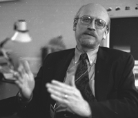
"The CRA has been very beneficial; I'm not just referring to funding and improved design benefits,
but to the benefits associated with the synergy between NASA and Boeing."
- Tom Wicks, Boeing Company
Today, the term "rotorcraft" is used for helicopters, tiltrotors, and other less conventional vertical take off and landing aircraft. This year marks the end of a three-year cooperative research agreement (CRA) among NASA, industry and academia that concentrates on the viability of using parallel computing to solve problems related to one of the biggest challenges in rotor design: determining the vibratory loads on a rotor hub and the airloads on the rotor blades. This information is needed to optimize the shape and structural properties of the rotor blade for efficient performance.
"The CRA has allowed us to make a giant step towards modeling rotor dynamics by leveraging eight years of Boeing investments that have been targeted towards the application of parallel and distributed computing to rotorcraft design," says Tom Wicks, manager of parallel and distributed systems at Boeing, participant in the CRA funded by NASA's HPCC Program. Other participants include International Business Machines (chair), Rensselaer Polytechnic Institute, Lockheed Missile and Space Research, Centric Engineering Systems, Intelligent Aerodynamics, Rice University, and Langley and Lewis Research Centers. HPCC has provided a metacenter for their research, which is currently made up of two systems, a 160-node IBM SP2 at NASA Ames Research Center and a 48-node SP2 at NASA Langley Research Center.
Rotor--first step
The complicated aerodynamic interactions taking place in rotorcraft flight have pushed the modeling envelope out for rotor blades to address interference aerodynamics -- including blade/wake proximity effects, shock-wave/boundary-layer interactions, and wing/fuselage proximity effects. All of these are necessary to estimate blade loads, rotor performance and acoustics. "Information gained from interference aerodynamics is necessary to estimate flow characteristics and associated forces on fuselage, wings, tail surfaces and other external components subjected to the rotor wake and separated flow regions," adds Dadone.
After a 12-year investment in Boeing High Performance Computing tool development, an eight-year focus on rotorcraft applications, and additional funding from HPCC, Boeing can now model and understand the physics behind some of these conditions.
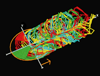
Graphical representations, including this picture of the wake systems
associated with each blade,
are developed by Boeing visualization scientist Dave Kerlick to help engineers understand blade vortex interaction.
Optimization process
This kind of physical modeling is what engineers have always needed for rotor design and optimization. The CRA focused on the three most computationally intensive elements of Boeing's rotor optimization process: comprehensive rotor analysis, rotor computational fluid dynamics (CFD) and structural optimization. (See Figure 1.) According to Boeing senior principal engineer Joseph Manke, who has led Boeing's effort on parallelization of rotor analysis and design applications, "the code modeling these details is computationally intensive. On parallel machines, considerable improvements have been made."

Comprehensive Rotor Analysis
The workhorse of the rotor optimization process is Boeing's comprehensive rotor analysis code which models, in detail, the coupled aerodynamics and mechanical dynamics of a rotor. A rotor blade is a very long flexible wing; so it flaps up, down and twists and therefore applies forces and moments to the rotor hub in response to aerodynamic and mechanical forces.
For example, the blade/wake proximity effects are important when a helicopter is landing. The free-wake model, developed by Continuum Dynamics, Inc. to analyze this very difficult flight condition, is one of many models in the comprehensive code. The free-wake models all the wake spirals that are important to the flow solution. To determine the wake shape, the free-wake model uses high-order vortex elements and wake relaxation.
Since this vortex method is computationally intensive, Manke and Boeing senior principal engineer Joel Hirsh implemented a parallel version of the vortex method. The principal idea behind parallelization is dividing algorithms into parts which can be calculated separately on different processors. Manke and Hirsh used the technique of message passing to distribute information among the processors of the IBM SP2. They benchmarked the parallel code on the IBM SP2. The results are summarized in Figure 2.; for the largest test case, linear speedup out to 64 processors was achieved.

Figure 2. Comprehensive Rotor Analysis and parallel free wake model
Manke and Hirsh were able to take the free-wake model to a new level of detail and simulate it on the IBM SP2 in a timeframe of practical use to Boeing engineers. "Before this parallelization, an analysis of rotor performance, vibration and noise, using an accurate wake calculation, took 80 hours," asserts Hirsh. "Now on the SP2, it only takes two to four hours." "Helicopter engineers are now free to exercise numerical wake models with only the best physics in mind and are not limited by the approximations caused by a lack of cost-effective computational power," says Byung Oh, Boeing senior principal engineer.
Rotor CFD and coupling
Rotor motions and deflections are calculated very accurately by Boeing. Certain aspects of the flow over the rotor cannot be captured by the models in the comprehensive rotor analysis code, so these details are computed by a rotor CFD analysis. The opportunity, according to Oh, "is integrating rotor motions and deflections with aerodynamic calculations, because in reality the aerodynamics would not be accurate enough if you didn't account for these motions and deflections. And by the same token, you wouldn't be able to compute these motions and deflections if the aerodynamics are not accurate." Rotor blades on Boeing's CH-47 helicopters and the blades of the 777 Ram Air Turbine are examples of designs that have used a comprehensive rotor analysis, complemented with a rotor CFD analysis.
Oh and Hirsh successfully coupled Boeing's comprehensive rotor code and the rotor CFD code called Full Potential Rotor (FPR), developed by NASA Ames' Aeroflightdynamics Directorate. They used the coupled codes to predict a 3D flow effect, called tip-relief, that the rotor code alone could not predict. "The FPR code coupled with the comprehensive rotor analysis code reached a major milestone in the last few months when Byung Oh gave it his stamp of approval," exclaims Manke. "This advance marks the first coupling of comprehensive rotor and rotor CFD codes that has proved practical."
Since the FPR code is computationally expensive, Hirsh and Manke implemented a parallel version and benchmarked the parallel code on the IBM SP2. The parallel Approximate Factorization method developed by Manke achieved maximum speedup out to 32 processors. Hirsh used message passing to extend the coupling methodology to the parallel versions of the comprehensive rotor code and FPR. According to Oh, "The direct coupling methodologies of rotor CFD and comprehensive rotor analysis that have been investigated in the NASA CRA will allow for better engineering support during the design cycle and will eventually permit structural optimization to minimize blade response to unsteady loads."
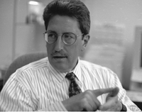
Boeing senior principal engineer Joseph Manke led Boeing's effort
on parallelization of rotor analysis and design applications.
Structural optimization
Boeing's structural optimization code implements a gradient-based optimization technique, a method that measures how the performance changes as each of the design variables is varied. This technique allows the search for feasible blade structural properties which minimize blade response in the presence of vibratory airloads. The airloads are computed by the comprehensive rotor code and can be evaluated for any flight condition within the range of validity of the aerodynamic models in the rotor code. This means that, if you have 90 design variables, you have to run the rotor code 90 times in order to compute the variation of the performance for each of the design variables. Suddenly the "two to four hour" turnaround resulting from parallelization on the SP2 takes on new meaning.
Hirsh implemented a parallel version of the structural optimization code in which the components of the gradient are computed in parallel. He benchmarked the parallel code on the IBM SP2. The parallel gradient method developed by Hirsh achieved maximum speedup out to 45 processors for the 90 design variable case.
Hirsh and Manke envision "a two-level parallel optimization strategy" in which the parallel versions of the comprehensive rotor code, the rotor CFD code and the structural optimization code are all used together. The maximum computing power of the IBM SP2 is essential to making this vision a reality.
Surrogate for FPR
The improved modeling achieved by coupling FPR to the comprehensive rotor code is important for optimization. However, the approach may not be practical for rotor design because of the computational cost of the CFD calculation. Boeing senior principal scientist Paul Frank solved this problem by replacing the FPR code with a model or "surrogate" based on a technology called Design and Analysis of Computer Experiments (DACE). In this approach, you construct a simple model of the relationship between the inputs/outputs of the FPR code by observing the outputs for a carefully selected set of inputs. Tests indicate that the DACE model-based surrogate FPR easily satisfies fidelity requirements for the rotor blade design process. In the context of Boeing's structural optimization code, the cost of generating the FPR model is quickly recovered because the surrogate FPR code is 200 times faster than the FPR code.
Visualization
Some of the results associated with the actual flow of the rotor are best represented with visualization. Boeing's visualization scientist Dave Kerlick has developed a way to apply virtual reality to blade modeling, allowing engineers to modify three-dimensional designs. "Fifteen years ago, graphics programming required writing code and recompiling it," Kerlick says. "Now modern visualization environments allow users to explore analysis data interactively, often without programming. It's a good environment for prototyping."
Wind-Tunnel Testing vs. Computational Predictions
Computer model simulation allows a lot more exploration and decision making before wind-tunnel testing. "Wind-tunnel testing can cost thousands of dollars an hour," says Dadone. "Look at, for example, the Bell-Boeing V-22 Osprey. The process began with the design of the rotor, wing, fuselage and other parts of the system using the best available tools. Since it was understood that the analytical tools were not accurate enough, a long series of experiments needed to be run to quantify and validate all of the elements of the integrated design. Experimentation began with wind tunnel tests and many different models of varying scope and complexity, culminated by a flight test program. Eventually you have to build the full-scale ship and fly it." Now, thanks to the Boeing/NASA partnership, there is a good way of improving the analytical predictions needed by the designer, which will eventually help to cut down on the number of wind-tunnel tests and on the hours of flight testing.
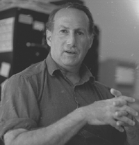
Boeing senior principal scientist Paul Frank reduced the computational
cost of the
CFD calculation by replacing the FPR code with a model or "surrogate."
Dadone warns against overblown expectations on how soon this method will replace wind-tunnel testing: "It's really a successful marriage between computer tools and wind-tunnel testing which benefits designers and manufacturers with early design results." Compared to the 'old method' of design, Dadone states that, "Boeing will be able to provide more accurate predictions in a shorter time. That translates into better time-to-market, which gives a tremendous competitive advantage."
"Before this parallelization, an analysis of rotor performance, vibration and noise,
using an accurate wake calculation, took 80 hours. Now on the SP2, it only takes two to four hours."
-Joel Hirsh, Boeing
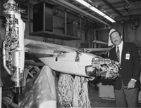
Boeing senior principal engineer Joel Hirsh discusses how the
Boeing/NASA partnership is improving the analytical predictions needed by the designer,
which helps target what experiments are needed in the wind tunnel including the use of the
Tiltrotor Test Stand at the Boeing Subsonic Wind Tunnel pictured above.
Synergy
With the help of the CRA and the performance of the IBM SP2 behind them, Wicks and team are trendsetters in this computational approach to design. "The CRA has been very beneficial; I'm not just referring to funding and improved design benefits, but to the benefits associated with the synergy between NASA and Boeing," adds Wicks. "Partnering with HPCC has provided for the continued development of the most sophisticated parallel computational tools, which gives Boeing the option to investigate the use of costly equipment without risk," says Ken Neves, computer science manager for Boeing.
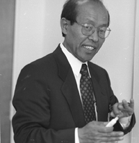
Boeing senior principal engineer Byung Oh gave the coupled modeling code
his stamp of approval.
This synergy has had far-reaching impact. For example, the computing methods have enabled Boeing to fix vibration or noise problems discovered after the production of a rotorcraft. In fact, with a good early grasp of detailed modeling in the design process, the Boeing team knows that they will be able to correct designs before they are built.
Expectations for the influence on everyday design have to be in sync with reality
though. "If you read the rationale for computational design, it says we can better
address noise and vibration problems relevant to high-performance rotorcraft. We have to
be realistic about what we can expect from the computer," says Manke. "It is not
a matter of running a code, and bang, we have our perfect design. It is more like running
a code and now we know what we really need to test."
![]()
The following information was extracted from a NASA's Insights Newsletter.
Send all comments to ![]() aeromaster@eng.fiu.edu
aeromaster@eng.fiu.edu
© 1995-98 ALLSTAR Network. All rights reserved worldwide.
Updated: February 23, 1999