 |
|||||
| Home | Research | For Teachers | HISTORY Level 1 Level 2 Level 3 |
PRINCIPLES Level 1 Level 2 Level 3 |
CAREER Level 1 Level 2 Level 3 |
| Gallery | Hot Links | What's New! | |||
| Web Administration and Tools | |||||
|
|||||
| Home | Research | For Teachers | HISTORY Level 1 Level 2 Level 3 |
PRINCIPLES Level 1 Level 2 Level 3 |
CAREER Level 1 Level 2 Level 3 |
| Gallery | Hot Links | What's New! | |||
| Web Administration and Tools | |||||
Navigation Systems - Level 3
![]()
A. GENERAL
The airway system is based primarily on the very high frequency omnidirectional range (VOR). This extensive system consists of several hundred ground stations that transmit navigation track guidance signals used by aircraft in flight.
The VOR navigational system has many advantages for the IFR pilot. The VOR transmits in the very high frequency range of 108.1 through 117.95 MegaHertz (MHz); therefore, it is relatively free from precipitation static and annoying interference caused by storms or other weather phenomena. Accuracy is another advantage: a track accuracy of plus or minus 1° is possible when flying a VOR radial. Wind drift is compensated for by flying to center the track bar indicator.
VOR signals are transmitted on line-of-sight. Any obstacles (buildings, mountains or other terrain features, including the curvature of the earth) block VOR signals and restrict the distance over which they are received at a given altitude. This can result in a sudden scalloping fluctuation of the cockpit indicators -normally for short time intervals. Certain terrain features may produce areas where VOR navigation signals are unusable, so every instrument pilot making an "off airways" flight should be aware of the restrictions along the route.
Because of greater reception distances at higher altitudes, it is possible for an aircraft to receive erroneous indications due to the reception of two VOR stations operating on the same frequency. Stations on the same frequency are spaced as far apart as possible, but there are, nevertheless, more VORs than the 160 frequencies available. The solution has been to design and classify VORs according to the usable cylindrical service volume.
This is the system by which VOR frequencies are assigned to stations far enough apart to prevent overlapping, confusing signals. As long as pilots use the proper chart, they are protected from interference between two VORs. The pilot uses low-altitude charts below 18,000 ft and the high-altitude charts at and above 18,000 ft.
B. VOR ACCURACY
1. REQUIREMENTS FOR CHECKS: The Air Regulations and good judgement dictate that the VOR equipment of aircraft flying under instrument flight rules be within specified tolerances. Airborne VOR equipment used on IFR flights must be maintained, checked and inspected under an approved procedure. The pilot normally makes these operational checks. In preparing for an IFR flight the pilot should check the aircraft instrument, then make a physical check on the appropriate VOT (test) frequency to determine whether the VOR equipment meets accuracy requirements.
2. VOR TEST FACILITY- The first method is to use a VOR test facility signal (VOT). This is an approved test signal, located on an airport, that enables the pilot to check the receivers conveniently and accurately. First, the pilot should tune the VOR receiver to the VOT frequency. These frequencies are coded with a series of Morse code dots or a continuous 1020-cycle tone. When the pilot sets the course selector to 0°, the track bar (TB) indicator should center and the TO-FROM indicator should read FROM. Then the pilot sets the selector to 180°. The TO-FROM indicator should read TO and the TB should be centered.
The pilot determines the exact error in the receiver by turning the track selector until the TB is centered, and noting the degrees difference between 180° or 0°. The maximum Permissible bearing error with this system check is plus or minus 4°. Apparent errors greater than 4° indicate that the aircraft receiver is beyond acceptable tolerance. In such circumstances the pilot should determine the cause of the error and have it corrected before attempting IFR flight.
The airports with VOT facilities are listed in the Airport/ Facility Directory. Because the VOT signal is only a special test signal, it may be received and used regardless of the aircraft's position on the airport.
3. VOR CHECK POINT SIGNS: A number of aerodromes have VOR check point signs located beside taxiways. These signs indicate a point on the aerodrome where there is sufficient signal strength from a VOR to check aircraft VOR equipment against the radial designated on the sign. Frequently a DME distance will also be indicated for check purposes. The maximum permissible difference between aircraft equipment and the designated radial is 4° and 0.5 NM of the posted distance.
4. DUAL VOR CHECK.- If neither a test signal (VOT) nor a designated check point on the surface is available and an aircraft is equipped with dual VORs (units independent of each other except for the antenna), the equipment may be checked against each other by tuning both sets of the same VOR facility and noting the indicated bearings to that station. A difference greater than 4° between the aircraft's two VOR receivers indicate that one of the aircraft's receivers may be beyond acceptable tolerance. In such circumstances, the cause of the error should be investigated and, if necessary, corrected before the equipment is used for an IFR flight.
 5. AIRBORNE VOR CHECK: Aircraft VOR equipment may also be checked
while airborne by flying over a fix or landmark located on a published radial and noting
the indicated radial. Equipment which varies more than 6° from the published radial
should not be used for IFR navigation.
5. AIRBORNE VOR CHECK: Aircraft VOR equipment may also be checked
while airborne by flying over a fix or landmark located on a published radial and noting
the indicated radial. Equipment which varies more than 6° from the published radial
should not be used for IFR navigation.
C. AIRCRAFT VOR COMPONENTS
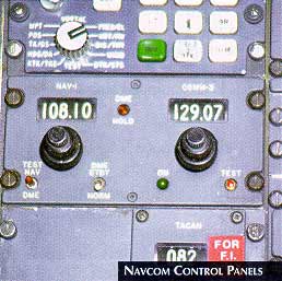
1. VOR RECEIVER: In many modern aircraft one control unit is used for both the VOR receiver and the VHF communications transceiver. When located together, the radio is called a NAVCOM (See Navcom Control Panels figure, on the right). The VOR signals are received on the antenna, normally located on the vertical stabilizer or on top of the fuselage. This antenna resembles a "V" lying in a horizontal plane. The VOR receiver converts signals from the antenna to the readings displayed on the navigation indicator.
2. NAVIGATION INDICATOR: The VOR navigation indicator gives the pilot aircraft position
information by means of three components. The track selector, sometimes called the omnibearing
selector or OBS, is used to rotate the azimuth ring, which displays the selected VOR
track, (See Navigation Indicator figure, below right).
This ring may also show the reciprocal of the selected track.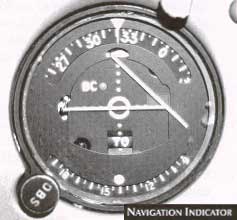
The TO-FROM/OFF flag indicates whether the track will take the pilot to or from the
station. If the aircraft is out of station range and cannot receive a reliable, usable
signal the TO-FROM/OFF indicator displays OFF. Also, the OFF flag is displayed when
the aircraft is directly over the station, when abeam of the station in the area of
ambiguity (i.e., directly on either side of the station) or when beyond the reception
range of the station selected.
When the aircraft heading agrees generally with the track selector, the track deviation bar (TB) shows the pilot the position relative to the track selected and indicates whether the radial is to the right or left. The TB needle has a l 0° spread from center to either side when receiving a VOR signal. The Track Bar Deflections figure (left), shows that an aircraft 5° off track would have the TB one-half of the way from center to the outside edge. If the aircraft is 10° off track the needle swings completely to one side. Each dot on the navigation indicator represents 2° when the pilot is flying VOR.
 3. TRACK ARROW: Each time a track is chosen on the selector, the
area around the VOR station is divided into halves or envelopes (see Left Right
Envelopes figure, on the right). It is helpful to think of the dividing line as a
track arrow, which runs through the station and points in the direction of the selected
track. The TB shows the pilot in which of these two envelopes the aircraft is located. If
the aircraft is flying along the track line, the TB needle is centered. If the aircraft
flies to the left of the track arrow (as in position A), the TB needle swings to
the right. If the aircraft moves to the right of the track arrow, (position B),
the TB needle swings to the left.
3. TRACK ARROW: Each time a track is chosen on the selector, the
area around the VOR station is divided into halves or envelopes (see Left Right
Envelopes figure, on the right). It is helpful to think of the dividing line as a
track arrow, which runs through the station and points in the direction of the selected
track. The TB shows the pilot in which of these two envelopes the aircraft is located. If
the aircraft is flying along the track line, the TB needle is centered. If the aircraft
flies to the left of the track arrow (as in position A), the TB needle swings to
the right. If the aircraft moves to the right of the track arrow, (position B),
the TB needle swings to the left.
Whenever the pilot changes the track selector, he or she should visualize an imaginary track arrow over the station. In this way, the pilot can look at the TB and tell in which envelope the aircraft is located.
 4. REFERENCE LINE: When the pilot selects a track, the position of
another line is established, a reference line perpendicular to the track arrow and
intersecting it at the station. The reference line divides the VOR reception area into two
additional sectors. The area forward of the reference line is the FROM envelope and the
area to the rear of the reference line is the TO envelope. The TO-FROM indicator shows in
which envelope the aircraft is located. In the To-From Envelopes figure,
on the right, both aircraft display a FROM reading.
4. REFERENCE LINE: When the pilot selects a track, the position of
another line is established, a reference line perpendicular to the track arrow and
intersecting it at the station. The reference line divides the VOR reception area into two
additional sectors. The area forward of the reference line is the FROM envelope and the
area to the rear of the reference line is the TO envelope. The TO-FROM indicator shows in
which envelope the aircraft is located. In the To-From Envelopes figure,
on the right, both aircraft display a FROM reading.
 The VOR Indications figure, on the left,
shows the readings that an aircraft would receive in eight different locations around the
VOR station. In position A, the aircraft shows a centered TB, indicating that it
is on track; the TO-FROM flag shows FROM. Position B shows a left TB and a FROM
indication.
The VOR Indications figure, on the left,
shows the readings that an aircraft would receive in eight different locations around the
VOR station. In position A, the aircraft shows a centered TB, indicating that it
is on track; the TO-FROM flag shows FROM. Position B shows a left TB and a FROM
indication.
Aircraft at positions C and G are in the area of ambiguity. In this area, the opposing reference signals that actuate the TO-FROM indicator cancel each other and produce an OFF Indication.
The area of ambiguity widens with increasing distance from the station. The greater the distance, the longer the TO-FROM flag will indicate OFF as the aircraft moves between the TO and FROM envelopes.
D. DETERMINATION OF POSITION
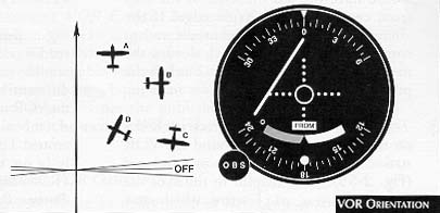 1. HEADING: Aircraft heading has absolutely no effect on the
readings of the VOR indicator. No matter which direction the aircraft is heading, the
pilot receives the same indication as long as the aircraft remains in the same track
envelope (see VOR Orientation figure, on the right).
1. HEADING: Aircraft heading has absolutely no effect on the
readings of the VOR indicator. No matter which direction the aircraft is heading, the
pilot receives the same indication as long as the aircraft remains in the same track
envelope (see VOR Orientation figure, on the right).
2. POSITION FIX: To determine a fix (without DME), the pilot must use two VOR stations because the VOR gives only direction and not distance from the station. First, the pilot should tune the number one VOR to one of the desired stations and make positive identification. Unless the pilot makes positive identification, that station should not be used. If a VOR station is shut down for maintenance or the signal is unreliable because of a malfunction, the navaid identification is not transmitted.
After identifying the station, the pilot should center the TB needle with the positive FROM indication on the TO-FROM/OFF flag.
 The pilot repeats this procedure with the other VOR station. Then,
using the chart, the pilot draws a line outbound from the VORs along the radials indicated
by the track selector. The intersection of these bearings is the aircraft's position (see
VOR Position Fix figure, on the right).
The pilot repeats this procedure with the other VOR station. Then,
using the chart, the pilot draws a line outbound from the VORs along the radials indicated
by the track selector. The intersection of these bearings is the aircraft's position (see
VOR Position Fix figure, on the right).
E. FLIGHT TO A VOR STATION
1. BRACKETING: Because there is generally a crosswind, the pilot rarely can intercept a radial, take up the heading of that track, and fly directly to the station. To stay on track, the pilot must make a series of small corrections. The process of intercepting a radial and making the corrections necessary to remain on track is called bracketing. The method described here minimizes the number of turns needed to determine the necessary wind correction, and requires the least attention by the pilot.
Figure Bracketing a VOR Radial, below right, shows the series of
maneuvers that a pilot uses in bracketing a radial to a VOR station. The pilot of the
aircraft in position l determines that the radial of the desired VOR station is
to the right and the pilot must turn right to intercept it. In position 2, the
pilot turns to an intercept angle of 30°. Since the radial is 090° to the station, the
intercept heading is 120° as shown on the heading indicator.
In position 3, the aircraft intercepts the radial. The pilot immediately turns the aircraft to a 090° heading to coincide with the inbound direction of the radial. While using the heading indicator to carefully bold the heading, the pilot in position 4 starts to drift off track. The pilot then takes up a new intercept heading of 070° a 20° intercept angle. The pilot flies this new intercept heading of 070° until re-intercepting the radial, at which time (position 7) he or she divides this intercept angle by two and then turns to the new heading which is 080°.
The new heading of 080° lets the aircraft drift a little north of track. This informs the pilot that the desired track heading must be somewhere between 090°, which allows the aircraft to drift south of the radial, and 080°, which takes the aircraft north of the radial. At no time from this point to the station will the pilot turn to a heading less than 080° or heading more than 090°.
As shown in position 9, the aircraft takes up the heading of 090°, which allows the aircraft to drift back onto the radial. As the aircraft intercepts the radial at position 10, the pilot turns to a heading between 090° and 080°, then proceeds to the station, tracking the radial with an aircraft heading 085° .
If the pilot takes up a specific intercept angle and then divides the angle by two, as necessary, the aircraft brackets the radial with the least number of turns and holds e track with the greatest accuracy.
TRACK TO THE STATION: The pilot should check the heading indicator against the magnetic compass when beginning to track. (The VOR indicator tells the pilot only the position of the aircraft relative to a certain radial and the pilot must rely upon the heading indicator for aircraft heading formation).
The most common use of VOR navigation to fly on a radial from station to station. The pilot selects a radial course on the OBS and tracks that radial by keeping the TB needle centered, which occurs as long as the BS is in general agreement with the heading indicator. For example, if the dial is to the right, the indicator will point the right, and the pilot must turn in this direction to intercept the radial.
As the aircraft passes the VOR station, the VOR receives two basic indications provided that the aircraft crosses directly over the station. The most positive indication is that TO-FROM indicator changes to the opposite reading. (TO to FROM). The second, less certain indication is the fluctuation of the TB. If the aircraft passes directly over the station, the needle fluctuates from side to side and returns to its original position. If the aircraft is left of track, the needle does not fluctuate, bur continues to point to the right. Likewise, if the aircraft is right of track, the needle will point to the left and not fluctuate as the aircraft passes abeam the station.
 TIME CHECK: Another use for VOR is to take a time check, which
informs the pilot of the time remaining to fly to a station. For example, while inbound to
the station on the 022° radial (See VOR Time Check figure, on the
right), the pilot wishes to estimate the time to the station. The pilot elects to use the
030° radial to begin the time check, and turns the aircraft to a heading of 120°, which
is at right angles to the 030° radial. The OBS is turned to 030° and as the needle
centers, the pilot notes the time. Immediately afterward, the pilot rotates the OBS to
040°, which is the next radial to be used in the time check. The pilot then continues to
bold the 120° aircraft heading and flies to the 040° radial. As the pilot crosses this
radial and the needle centers, he or she notes the time and finds that it has taken two
minutes (120 seconds) to make the 10° radial change.
TIME CHECK: Another use for VOR is to take a time check, which
informs the pilot of the time remaining to fly to a station. For example, while inbound to
the station on the 022° radial (See VOR Time Check figure, on the
right), the pilot wishes to estimate the time to the station. The pilot elects to use the
030° radial to begin the time check, and turns the aircraft to a heading of 120°, which
is at right angles to the 030° radial. The OBS is turned to 030° and as the needle
centers, the pilot notes the time. Immediately afterward, the pilot rotates the OBS to
040°, which is the next radial to be used in the time check. The pilot then continues to
bold the 120° aircraft heading and flies to the 040° radial. As the pilot crosses this
radial and the needle centers, he or she notes the time and finds that it has taken two
minutes (120 seconds) to make the 10° radial change.
The formula for determining the time remaining to the station is:
(TIME IN SECONDS BETWEEN RADIAL CHANGE)/(DEGREES OF RADIAL CHANGE) equals TIME TO STATION IN MINUTES.
Therefore, by dividing 120 seconds by 10, the pilot finds that there are 12 minutes remaining to fly to the station. Although this problem can be worked out using any degree of radial change, l0 degrees of radial change is the simplest and fastest to compute.
Send all comments to ![]() aeromaster@eng.fiu.edu
aeromaster@eng.fiu.edu
© 1995-98 ALLSTAR Network. All rights reserved worldwide.
| Funded in part by |
Updated: February 23, 1999