 |
|||||
| Home | Research | For Teachers | HISTORY Level 1 Level 2 Level 3 |
PRINCIPLES Level 1 Level 2 Level 3 |
CAREER Level 1 Level 2 Level 3 |
| Gallery | Hot Links | What's New! | |||
| Web Administration and Tools | |||||
|
|||||
| Home | Research | For Teachers | HISTORY Level 1 Level 2 Level 3 |
PRINCIPLES Level 1 Level 2 Level 3 |
CAREER Level 1 Level 2 Level 3 |
| Gallery | Hot Links | What's New! | |||
| Web Administration and Tools | |||||
Navigation Systems - Level 3
![]()
A. GENERAL
Area Navigation (RNAV) can be defined as a method of navigation that permits aircraft operation on any desired course within the coverage of station-referenced navigation signals or within the limits of a self contained system capability, or a combination of these.
RNAV was developed to provide more lateral freedom and thus more complete use of available airspace. This method of navigation does not require a track directly to or from any specific radio navigation aid, and has three principal applications:
Navigation systems which provide RNAV capability include VOR/DME, DME/DME, LORAN C, GPS, OMEGA and self contained Inertial Navigation Systems (INS) or Inertial Reference Systems (IRS).
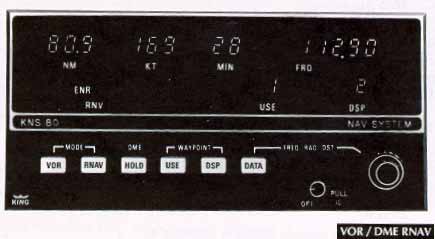
B. VOR/DME
A common general aviation RNAV system is the track-line computer (TLC), based on azimuth and distance information from a VORTAC. It is also called the RHO-THETA system. With the track-line computer the pilot effectively moves or off-sets the VORTAC to any desired location if it is within reception range. This "phantom station" is created by setting the distance (RHO) and the bearing (THETA) of the waypoint from a convenient VORTAC in the appropriate windows of the waypoint selector (see VOR/DME RNA figure, below). A series of these "phantom stations" or waypoints make up an RNAV route.
The Area Navigation Route figure, below, illustrates how the VOR/DME RNAV is used to navigate from Belgrade to Haines on a direct route. This route crosses the 180ş radial 23 NM south of the Mystic VORTAC. Therefore, the pilot sets waypoint #1 as 180/23 on the control panel. Waypoint #2 is 15 nautical miles (NM) from MEEKER VORTAC on the 360ş radial, or 360/15 on the panel. Waypoint #3 is 360/22.
The direct route from Belgrade to Haines is 191 NM, 24 NM less than the VICTOR airway route.
The pilot could also place waypoint #3 on the destination airport, allowing navigation from waypoint #2 direct to the Haines airport. The DME readout would give a constant indication of the remaining distance to the destination. The pilot would specify waypoint #3 as 064/49 (in reference to the MILTON VORTAC). Modern Flight Management Systems (FMS) often use DME/DME (RHO-RHO) systems which compare numerous DME signals (when coverage is available) to provide position and time and distance information.
C. LORAN-C
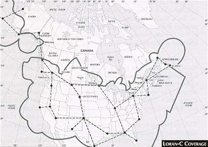
LORAN-C is a pulsed hyperbolic system operating in the 90 to 110 kilohertz (kHz) frequency band which is used for marine and air navigation where signal coverage is available. The system is based upon the measurement of the time difference in the arrival of signal pulses from a group or chain of stations. A chain consists of a master station linked to a maximum of four secondary stations with all of the signals synchronized with the master. The LORAN-C receiver measures the time difference between the master and at least two of the secondaries to provide a position fix.
The North American LORAN-C coverage area is limited to the continental United States, southern Canada and the east and west coasts (see Loran-C Coverage figure, below).
LORAN-C system inaccuracies are mainly attributable to distance from the ground station, receiver geometry relative to ground transmitter baselines, and propagation anomalies associated with the earth's surface.
Because of the good repeatable accuracy of LORAN-C where adequate signal strength is available, the system has the potential to be used for non-precision approaches. Most LORAN-C receivers used in general aviation are approved for VFR use only. Equipment that is approved for IFR use should be clearly indicated in the aircraft or in the aircraft log books. It is the pilot's responsibility to ascertain the IFR approval status of installed LORAN-C equipment before commencing an IFR flight.
D. GPS (GLOBAL POSITIONING SYSTEM)
GPS is a satellite positioning system developed by the United States Department of Defense (DOD) for use on land, sea and in the air. It will likely be the major component of the ICAO - designated GNSS - Global Navigation Satellite System. The full GPS constellation has 24 operational satellites to provide continuous, highly accurate three-dimensional position information globally. The Russian GLONASS system and European INMARSAT may add satellites to the GNSS constellation to provide redundancy.
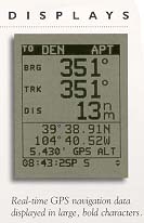
1. How DOES GPS WORK?: Operating in l 1,900 NM orbits, each satellite continuously transmits signals on 1227.6 and 1575.42 MHz. The GPS receiver automatically selects the signals from four or more satellites to calculate a three-dimensional position, velocity and time. Using the un-encrypted coarse acquisition navigational signal (C/A code) which will be available to all civil users, system accuracy will be at least 100 meters horizontally and 140 metres vertically, 95% of the time. Unlike ground based navigation systems, GPS provides global coverage with virtually no signal inaccuracies associated with propagation in the earth's atmosphere. Signal masking can occur with mountainous terrain, man-made structures and with poor antenna location on the aircraft. It is significant that GPS accuracy is better than anything we have had before for en route and non-precision approach guidance.
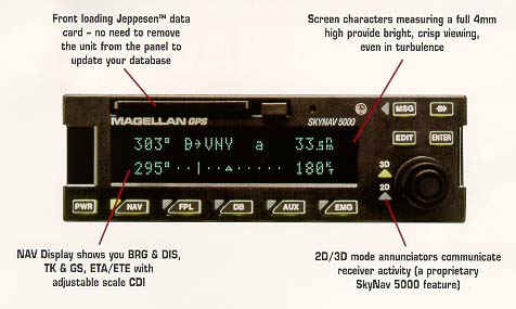
Example of a panel mounted GPS without moving map features
Each GPS satellite has 4 atomic clocks on board, because precise timing is the key to GPS navigation; this guarantees an accuracy of one nanosecond, or one billionth of a second. The satellites broadcast this time along with data used by receivers to calculate satellite position.
Stations located around the world monitor the performance of the satellites, and a master control station in Colorado Springs has the capability to send up corrections if errors are detected.
In addition to accurate 3-D position information, GPS also gives a direct reading of velocity - both speed and direction of motion. This means that displayed groundspeeds are very responsive to actual speed changes, and pilots will notice a marked improvement over groundspeeds generated by DME or LORAN-C. The availability of direction of motion allows quicker warning of off-course deviations, making for smoother operation.
2. DIFFERENTIAL GPS: Differential techniques can be used to achieve the accuracy required for more demanding operations. This is done by locating a receiver on the ground at a precisely-surveyed position. This receiver is also able to calculate the errors in the satellite signals. These errors can be data linked to aircraft in the form of corrections which can be applied by the aircraft receiver to reduce position error to as low as 2 to 5 metres.
There are two types of differential, local and wide. Local is essentially described above. Wide area differential would use ground stations spaced hundreds of miles apart feeding a master control station which would send correction data up to geostationary satellites.
3. ACCURACY AVAILABILITY AND INTEGRITY: Aviation navigation systems must meet stringent accuracy, availability and integrity requirements. Accuracy and availability are obvious. Integrity is the ability of the system to warn a user when there is something wrong with the system. For example, ILS signals are monitored electronically, and if the monitors detect a malfunction they must shut down the ILS within 6 seconds. This results in a flag on the flight deck and a missed approach.
One way to achieve integrity is through receiver design, and the GPS receiver TSO C-129 calls for Receiver Autonomous Integrity Monitoring (RAIM). RAIM requires at least 6 satellites in view. The more the better. RAIM works by comparing position solutions using different combinations of satellites. Comparing these solutions can lead to the conclusion that a satellite is broadcasting incorrect data, and the receiver can then ignore that satellite.
.WARNING.
Only GPS receivers which meet TSO C-129 are currently approved as the primary navaid for IFR operations. If this standard is not met, grossly incorrect data may be supplied by the satellite with no error indication.
4. GPS APPROACHES: GPS is approved for non-precision approaches (NPAs), including VOR, VOR/DME, NDB and NDB/DME. This approval is subject to certain criteria:
Using differential techniques, GPS should be capable of providing sufficiently accurate and reliable data, to allow precision approaches to Category I minima. It is theoretically possible that GPS could even be used for Category II or III approaches; however, it is not certain if all the integrity issues necessary for these approaches can be resolved.
5. EN ROUTE AND TERMINAL OPERATIONS: GPS may be used as the primary IFR flight guidance for oceanic, domestic en-route and terminal operations if the following provisions and limitations are met:
NOTE. If there is a discrepancy between GPS and the traditional NAVAID(s), the Pilot must revert to the traditional NAVAID(s) for navigation.
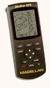

Examples of hand held GPS systems and screen
E. OMEGA Network
Omega is a network of eight VLF transmitting stations located throughout the world to provide worldwide signal coverage for marine and air navigation. These stations transmit precisely timed signals in the VLF band (10-13 kHz). Because of the low frequency, signals can be received to ranges of thousands of miles. Omega signals are affected by propagation variables which may degrade fix accuracy. These variables include daily variation of phase velocity, polar cap absorption, and sudden solar activity. Precipitation static and other electrical activity can also affect system operation. Omega provides a normal system accuracy of 2 to 4 NM worldwide.
With certain limitations, OMEGA navigation systems are approved for en route IFR within most classes of RNAV airspace. OMEGA is not approved for instrument approach procedures.
F. INS (INERTIAL NAVIGATION SYSTEM)
THE SYSTEM: Inertial Navigation Systems (INS) are completely self-contained and independent of ground based navigation aids. After being supplied with initial position information, it is capable of updating with accurate displays of position, attitude, and heading. It can calculate the track and distance between two points, display cross error, provide ETAs, ground speed and wind information. It can also provide guidance and steering information for the pilot instruments.
The system consists of the inertial platform, interior accelerometers and a computer. The platform, which senses the movement of the aircraft over the ground, contains two gyroscopes. These maintain their orientation in space while the accelerometers sense all direction changes and rate of movement. The information from the accelerometers and gyroscopes is sent to the computer, which corrects the track to allow for such factors as the rotation of the earth, the drift of the aircraft, speed, and rate of turn. The aircraft's attitude instruments may also be linked to the inertial platform.
The accuracy of the INS is dependent on the accuracy of the initial position information programmed into the system. Therefore, system alignment before flight is very important. Accuracy is very high initially following alignment, and decays with time at the rate of about 1-2 NM per hour. Position updates can be accomplished in flight using ground based references with manual input or by automatic update using multiple DME or VOR inputs.
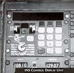 2. OPERATION: To operate a typical system, power is applied and the
INS is activated. As the gyro's spin up and the platform is aligned with the aircraft's
attitude, a keyboard (see INS Control Display Unit figure, on the right)
is used to advise the system of the aircraft's present position, normally in terms of
latitude and longitude, and magnetic variation. This information is integrated into a
mathematical model within the computer and, by a procedure known as gyrocompassing,
the system reckons its north reference point.
2. OPERATION: To operate a typical system, power is applied and the
INS is activated. As the gyro's spin up and the platform is aligned with the aircraft's
attitude, a keyboard (see INS Control Display Unit figure, on the right)
is used to advise the system of the aircraft's present position, normally in terms of
latitude and longitude, and magnetic variation. This information is integrated into a
mathematical model within the computer and, by a procedure known as gyrocompassing,
the system reckons its north reference point.
As the system is aligning, the co-ordinates of each waypoint along a planned route are entered into the computer. Additional information such as ground tracks, ground speed, and desired ETAs may also be entered in some systems.
Once airborne, the required information is normally displayed on a control display unit (CDU) in either a CRT or digital format (see INS Control Display Unit figure, above right). The INS may also be interfaced with other equipment and instruments in the aircraft. For example, a HSI may receive and display the information or an autopilot may be connected to the INS so the navigation information may be used to maneuver the aircraft.
En route, the pilot recalls the desired waypoint from the computer. The computer provides and displays steering and distance information to the aircraft's normal navigation instruments. Alterations or deviations from the preplanned route may be carried out by simply entering the coordinates of the new desired waypoint into the computer.
3. ERRORS: Many factors contribute to errors in an inertial navigation system. In-flight errors arise from imperfections in gyros, accelerometers and computers. Initial misalignment may cause additional errors. Some errors and their effects are discussed in the following paragraphs.
Initial Leveling. If the platform is not correctly leveled the resultant tilt angle will allow the accelerometer to "see" the effect of gravity and thus have outputs besides true vehicle accelerations. The result of this is distance errors.
Accelerometers. The imperfect sensitivity and alignment of the accelerometers from which all information is drawn will lead to velocity and distance errors.
Integrator Errors. Integration errors may be due to drift, faulty calibration, non-linearity of errors in the initial conditions established (rounding off in the equation). Depending on which stage of integration the errors occur, they may or may not increase with time and may be in any of the vc1ocity, distance or position solutions.
Initial Azimuth Misalignment. An error due to, misalignment in azimuth will give rise to velocity errors. Once integrated these velocity errors will lead to ever increasing distance and position errors.
Leveling Gyro Drift. The random precession of gyros will tend to turn the platform away from the horizontal causing an oscillation action as the accelerometers try to correct. This oscillation, depending on its period, will cause velocity and subsequent distance errors.
Azimuth Gyro Drift. Small position errors may occur due to azimuth gyro drift. However, gyro drift about the azimuth axis produces in-flight azimuth errors that are small compared to the initial misalignment errors in azimuth.
Computer Errors. Errors in the computer are attributable to two basic causes; hardware limitations and approximations made in deriving equations. As modern digital computers eliminate most hardware/software problems only minor approximation errors remain.
4. RING LASER GYRO (RLG): The ring laser gyro is a triangle shaped device with a silicone body and a gas filled cavity. A cathode and two anodes are used to excite the gas and produce two laser beams travelling in opposite directions. Reflectors in each corner are used to reflect the lasers around the unit's body.
If the two laser beams travel the same distance, there will be no change in their frequency. However, if the unit is moved (accelerated), one light beam will travel a greater distance to the detector than the other beam. The beam travelling the greater distance will have a lower frequency than the beam travelling the shorter distance. The detector analyzes these frequency changes and sends the information to the computer, which then translates the data into movement in space.
5. RING LASER GYRO IN AN INS: By using three ring laser gyros and three accelerometers placed at right angles, it is possible to interpret all movement of the aircraft in space. This type of system has no moving parts and makes it ideal for "strapdown" inertial systems.
 6. THE STRAPDOWN INS: A strapdown INS is one that is "hard
mounted" to the aircraft. There is no need for a stabilized platform such as
that utilized in a conventional INS (see INS Mounting figure, on the
right).
6. THE STRAPDOWN INS: A strapdown INS is one that is "hard
mounted" to the aircraft. There is no need for a stabilized platform such as
that utilized in a conventional INS (see INS Mounting figure, on the
right).
As the aircraft flies along, the ring laser gyros detect vertical acceleration, beading and velocity changes. Rather than continuously repositioning the sensor package, as in a conventional system, the computer recognizes the changes and mathematically processes them. By using computer software to maintain the inertial references, the stabilized platform with its motors, gimbals and angular measuring devices is eliminated.
7. ADVANTAGES OF A RLG.- The ring laser gyro INS combines high accuracy, low power requirements, small size and light weight with an instant alignment capability. In addition, because there are no moving parts involved, the ring laser gyros INS generally has a very high serviceability rate.
8. PILOT PROCEDURES: Most gross navigational errors associated with INS or ONS navigation involve pilot error rather than equipment error. It is extremely important that proper INS procedures are followed when entering waypoints and using the INS for navigation. In particular, cross-check of all data by both pilots is essential prior to entering it into the system for navigation. See the North Atlantic MNPS Operations Manual for more detailed guidance.
G. FMS (FLIGHT MANAGEMENT SYSTEMS)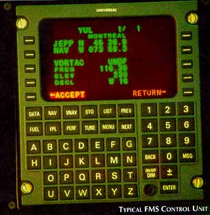
Flight management system (FMS) is the term used to describe an integrated system that uses navigation, atmospheric and fuel flow data from several sensors to provide a centralized control system for flight planning, and flight and fuel management. The system processes navigation data to calculate and update a best computed position based on the known system accuracy and reliability of the input sensors. This system may also be referred to as a multi-sensor RNAV. FMS controls differ widely between aircraft types and manufacturers, but the Typical FMS Control Unit figure, on the right, gives a typical arrangement.
The heart of any FMS is the navigation computer unit. It contains the micro processor and navigation data base. A typical base contains a regional or worldwide library of navaids, waypoints, airports and airways.
FMS sensor input is supplied from external DME, VOR, air data computer (ADC) and fuel flow sensors. Usually one or more long range sensors such as INS, IRS, ONS, LORAN-C or GPS are also incorporated. Depending on the capabilities of the navigation sensors, most flight management systems are approved for en route IFR in most classes of RNAV airspace.
H. AIRSPACE Using RNAV
With the development of reliable and accurate RNAV systems, both domestic and oceanic airspace were reorganized to make use of rigid RNAV performance specifications. Examples of current RNAV airspace are:
Send all comments to ![]() aeromaster@eng.fiu.edu
aeromaster@eng.fiu.edu
© 1995-98 ALLSTAR Network. All rights reserved worldwide.
| Funded in part by |
Updated: February 23, 1999