 |
|||||
| Home | Research | For Teachers | HISTORY Level 1 Level 2 Level 3 |
PRINCIPLES Level 1 Level 2 Level 3 |
CAREER Level 1 Level 2 Level 3 |
| Gallery | Hot Links | What's New! | |||
| Web Administration and Tools | |||||
|
|||||
| Home | Research | For Teachers | HISTORY Level 1 Level 2 Level 3 |
PRINCIPLES Level 1 Level 2 Level 3 |
CAREER Level 1 Level 2 Level 3 |
| Gallery | Hot Links | What's New! | |||
| Web Administration and Tools | |||||
Navigation Systems - Level 3
![]()
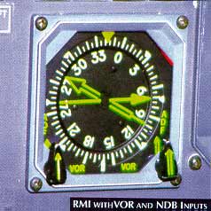
Many radio magnetic indicator (RMI) systems are designed for use with either an ADF or VOR station by selecting with a switch either VOR or ADF (see RMI with VOR and NDB Inputs figure, below).
The radio magnetic indicator (RMI) is both a bearing indicator and a heading indicator (see Radio Magnetic Indicator figure, below). The heading indicator uses "slaved gyro", i.e., the heading indicator is connected to a remotely located magnetic compass and is automatically "fed" directional signals. The heading indicator always shows the direction of the aircraft in relation to magnetic north.
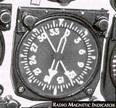
Therefore, the pointer of the bearing indicator always displays the actual magnetic bearing to the non-directional beacon. The tail of the pointer indicates the reciprocal bearing. This system lessens the pilot's task and further minimizes the possibility of errors.
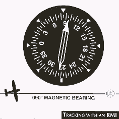
The RMI further simplifies tracking to a station because the pilot needs to refer to only one instrument instead of two. The pilot determines the magnetic heading by looking at the heading indicated on the azimuth card, and the magnetic bearing shown by the pointer. The aircraft heading used to compensate for wind drift does not influence the magnetic bearing as long as the aircraft remains on the bearing. As shown in the Tracking with an RMI figure, below, the pilot flying eastbound on the 095° magnetic bearing with 10° of north wind correction sees a display on the RMI of 085° magnetic heading (aircraft heading) and 095° magnetic bearing (to the station).
Send all comments to ![]() aeromaster@eng.fiu.edu
aeromaster@eng.fiu.edu
© 1995-98 ALLSTAR Network. All rights reserved worldwide.
| Funded in part by |
Updated: February 23, 1999