 |
|||||
| Home | Research | For Teachers | HISTORY Level 1 Level 2 Level 3 |
PRINCIPLES Level 1 Level 2 Level 3 |
CAREER Level 1 Level 2 Level 3 |
| Gallery | Hot Links | What's New! | |||
| Web Administration and Tools | |||||
|
|||||
| Home | Research | For Teachers | HISTORY Level 1 Level 2 Level 3 |
PRINCIPLES Level 1 Level 2 Level 3 |
CAREER Level 1 Level 2 Level 3 |
| Gallery | Hot Links | What's New! | |||
| Web Administration and Tools | |||||
Flight Instruments - Level 3
![]()
A. TRAFFIC ALERT AND COLLISION AVOIDANCE SYSTEM (TCAS)
1. OVERVIEW: The Traffic Alert and Collision Avoidance System (TCAS) is an independent airborne system. It is also known as Airborne Collision Avoidance System (ACAS). It is designed to act as a backup to the ATC system and the "see and avoid" concept. TCAS consists of four aircraft mounted antennas, a TCAS- Computer Unit and Mode S Transponder, and displays and controls in the cockpit. TCAS II continually surveys the airspace around an aircraft, seeking replies from other aircraft in the vicinity via their ATC transponders. The transponder replies are tracked by the TCAS system. Flight paths are predicted based upon these tracks. Paths predicted to penetrate a Collision Area surrounding the TCAS II aircraft are annunciated by TCAS. TCAS generates two types of annunciations: a Traffic Advisory or TA and a Resolution Advisory or RA. TCAS provides a time based alert in that the physical dimensions of a Caution Area will vary as a function of closure speed.
TCAS continuously calculates tracked aircraft projected positions. TAs and RAs are therefore constantly updated and provide real time advisory and position information.
A Traffic Advisory is displayed 35-48 seconds from the time the intruder aircraft is predicted to enter the TCAS aircraft's collision area. The traffic displayed includes the range, bearing and altitude of the intruder relative to the TCAS aircraft. The flight crew is to use this information as an aid to visually locate the intruder in order to avoid a conflict.
TCAS II also monitors a time based dimension of a Warning Area that extends 20-30 seconds from the time at which an intruder would enter the TCAS aircraft's collision area. Should an intruder enter the Warning Area, an escape strategy in the form of a Resolution Advisory is issued by the system. The Resolution Advisory is a vertical maneuver recommended to be performed or to be avoided by TCAS II in order to increase or maintain vertical separation relative to an intruding aircraft. TCAS III can also order horizontal maneuvers. The RA will be annunciated both visually and aurally. It will consist of either a corrective advisory, calling for a change in aircraft vertical speed, or a preventive advisory, restricting vertical speed changes.
Once the flight path of the intruder no longer conflicts with the collision area of the TCAS aircraft, TCAS will announce "CLEAR OF CONFLICT" to confirm the encounter has ended. The flight crew should then return to the original clearance profile.
TCAS generates Resolution Advisories and Traffic Advisories against intruder aircraft with ATC transponders replying in Mode C and Mode S. These include altitude in their transmissions. TCAS uses the altitude information for Resolution Advisory computations. TCAS can generate only Traffic Advisories against intruder aircraft whose transponders reply in Mode A (non-altitude reporting).
WARNING: TCAS cannot provide an alert for traffic conflicts with aircraft without operating transponders.
2. TCAS TRAFFIC ADVISORY DISPLAY: TCAS traffic can be displayed on a liquid crystal,
flat panel TA/RA/VSl which replaces the conventional IVSI (TCAS Climb Resolution
Advisory figure, below right). In this indicator the VERTICAL
SPEED INDICATOR (VSI) takes on the additional function of displaying traffic and
Resolution Advisories, in addition to other traffic information designed to improve
situation awareness. Internal switching of TCAS automatically presents a TCAS Traffic
Display on the VSI when a Traffic Advisory is necessary.
A white airplane symbol is displayed in the lower center of the VSI representing your TCAS equipped aircraft. A white range ring made up of 12 dots, each corresponding to a normal clock position, is included. The range ring surrounds the airplane with a radius of 2 nautical miles and is intended to assist in interpreting TCAS traffic information.
TCAS provides color-coded visual advisory areas just inside, and adjacent to, the VSI scale. These color-coded indications instruct the pilot what vertical speed region is TO BE AVOIDED (RED). If a change in vertical speed is necessary, the specific region of vertical speed the pilot is to "fly-to" is illuminated in GREEN. For example, in the event of the corrective advisory message "CLIMB - CLIMB - CLIMB", the PROHIBITED RED Vertical Speed region may extend from the extreme limit of descent to +1500 FPM as illustrated in TCAS Climb Resolution Advisory figure, right. The GREEN "fly-to" area appears from +1500 fpm to +2000 fpm.
In TCAS Climb Resolution Advisory figure (above, right), resolution advisory (RA) traffic (red square) is shown as 300 feet below and descending. Traffic advisory (TA) traffic (yellow circle) is shown as 500 feet below and descending while proximate traffic (cyan diamond) is shown as 1200 feet below and descending.
3. PILOT CONSIDERATIONS: Anytime a pilot deviates from a cleared altitude to follow a TCAS Resolution Advisory he or she should inform ATC as soon as possible of the deviation and return to the assigned altitude as soon as possible, after the traffic has passed. Ground Proximity Warning Systems (GPWS) advisories take precedence over TCAS advisories.
If stick shaker occurs during a RA maneuver, the pilot should immediately abandon the RA maneuver and execute the stall recovery procedure.
B. HEAD-UP DISPLAY (HUD)
A head-up display (HUD) is an electro-optical device which displays flight information near the front windscreen so that the pilot can simultaneously monitor aircraft instruments and the outside (forward) environment.
A HUD receives aircraft control, performance and navigation data from on-board computers and sensors. The information received is then projected onto a combining glass for head-up viewing. HUD symbology is focused at infinity for optimum effectiveness and pilot comfort. Often, information is presented in digital form. Aircraft pitch information is displayed as stylized pitch lines (pitch ladder).
ADVANTAGES
The most significant advantage of a HUD is the ability of the pilot to monitor flight and navigation data while being "head-up". This advantage is intuitively obvious in the situation of an approach to an airport in IMC near minimums, or while flying in VMC in a busy terminal area. Aircraft control is less likely to suffer while the pilot is looking for the runway environment, and the transition from instruments to visual references is easier.
DISADVANTAGES
Multitudes of information can be displayed on a HUD (see Typical
HUD Display figure, below right). However, the size limitation
of a HUD display has an enormous effect on the "user friendliness" of a HUD. If
analogue displays are used the symbology becomes very active and cluttered. If digital
displays are used the pilot is denied quick trend information thereby increasing pilot
workload during flight. Digital airspeed and altitude readouts cause the greatest
consternation. In the very latest generation of aircraft, this problem has been somewhat
overcome with the adoption of the "wide-angle" HUD.
Although the centralization of information on a HUD reduces the amount of head movements required during instrument flight, the crosscheck can break down if the pilot does not continue a disciplined scan of individual readouts within the HUD. Because the symbols displayed on the HUD are relatively small and very close together there appears to be a subconscious tendency to stare at the HUD without actually being aware of flight parameters ("magic fixation").
A HUD requires a suitable background in order for the pilot to see the projected display. "Washout" of HUD symbology can occur in high light intensity situations such as when pointing into the sun or when on short final at night (due to runway and approach lighting). Also, because of the nature of a HUD, colored backgrounds cannot be used to enhance the display. For instance, the difference between a nose high and nose low pitch attitude is not as apparent (in IMC) looking at a HUD as it is looking at a conventional attitude indicator with its blue sky and black ground hemispheres.
An additional problem with a HUD occurs when the background lighting intensity constantly changes, as when flying in and out of cloud or precipitation. Prolonged exposure to this situation can cause eye fatigue and in extreme cases may cause air sickness or disorientation.
SUMMARY: Although the HUD is a less-than-perfect electro-optical system, the benefits of a HUD far outweigh the disadvantages. For this reason some new transport aircraft are HUD equipped.
C. WEATHER RADAR
This section will provide a brief overview of weather radar from theory of operation to operation in-flight. The use of weather radar is often the most effective way of avoiding severe weather in the IFR environment. Although ATC makes every effort to advise pilots of areas of severe weather and steer them around it, it is the pilot's responsibility to avoid severe weather.
CAUTION: Weather radar should not be operated during refueling or when people on the ground are within at least 50 feet of the nose of the aircraft.
THEORY OF OPERATION
The primary use of weather radar is to aid the pilot in avoiding thunderstorms and associated turbulence. It is for avoiding - not penetrating -severe weather. Whether to fly into an area of radar echoes depends on echo intensity, spacing between the echoes, and the capabilities of both pilot and aircraft. Remember that weather radar detects only precipitation drops; it does not detect minute cloud droplets. A clear area on the radar screen does not mean that this area does not contain cloud. The geometry of the weather radar radiated beam precludes its use for reliable proximity warning or anti-collision protection. The beam is characterized as a cone-shaped pencil beam much like that of a flashlight or spotlight beam.
As mentioned earlier, only precipitation (or objects more dense than water such as earth or solid structures) will be displayed on the indicator. The best radar reflectors are raindrops and wet hail. The larger the raindrop, the better it reflects. Because large drops in a concentrated area are characteristic of a thunderstorm, the radar displays the storm as a strong echo. Generally, ice, dry snow and dry hail have low reflective levels and often will not be displayed by the radar.
Color radars show intensity of echoes by using colors, usually red or magenta as the
most severe (see Weather Radar Display figure, below
right). Monochrome radars use the brightness of the display to indicate
intensity.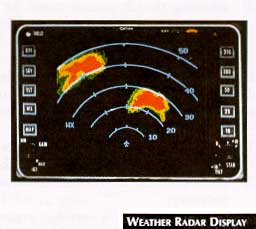
Extreme weather can usually be identified by characteristic patterns: (1) fingers and protrusions; (2) hooks; (3) scalloped edges; and (4) U-shaped cloud edges.
ATTENUATION
An extremely important phenomenon for the pilot to understand is that of attenuation. When a radar pulse is transmitted into the atmosphere, it is progressively absorbed and scattered so that it loses its ability to return to the antenna. This attenuation or weakening of the radar pulse is caused by two primary sources: distance and precipitation.
Attenuation because of distance is due to the fact that the radar energy leaving the antenna is inversely proportional to the square of the distance. For example, the reflected radar energy from a target 60 miles away will be one-fourth of the reflected energy from a target 30 miles away.
Attenuation due to precipitation is far more intense and is less predictable. Since some of the beam energy is absorbed by precipitation, the beam may not reach completely through the area of precipitation. If the beam has been fully attenuated, the radar display will show a "radar shadow" which appears as an end to the precipitation when, in fact, the heavy rain may extend for many more miles.
OPERATION IN-FLIGHT
Effective tilt management is the single most important key to more informative weather radar displays. Three factors should be remembered when using tilt controls:
In planning deviations, remember to plan for the deviation early. The following are some considerations for planning your deviation:
SUMMARY
To master the use of weather radar takes time and patience as well as understanding the particular characteristics of the radar set you operate. Use the operating handbook for your particular system to ensure greatest safety.
STORMSCOPE
The Stormscope (see Stormscope figure, below right)
is a weather avoidance system that detects electrical discharges from thunderstorms and
presents them on a display, usually a cathode ray tube (CRT). The system normally consists
of an antenna, a system processor, and the CRT.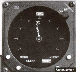
The loop and sense antenna detects electrical and magnetic fields produced by lighting. The high speed processor uses information from the antenna to determine distance and direction of electrical discharges about the aircraft.
A green CRT displays a lightning discharge as an. individual. point; a dense arrangement of points indicates sever weather. The CRT operates in various ranges: 25, 50, 100 and 200 nm being a standard set-up.
D. MODE "S" TRANSPONDER
The Mode S transponder is the latest generation transponder and is now the standard. Required for carriage in transport aircraft. The Mode S transponder provides the functions of existing ATCRBS transponders; (Modes A and C; identification and altitude reporting) bur because of its design characteristics, is able to do so in a more efficient manner.
Each Mode S transponder is assigned its own unique 24-bit interrogation address which allows it to be individually interrogated. The use of 24-bit address provides for more than 16 million different addresses, enough to ensure no duplication occurs.
Each interrogation contains the unique address of the aircraft for which it is intended. A Mode S transponder receiving an interrogation examines it for its own address. If the address corresponds, the transponder generates and transmits the necessary reply; all other aircraft ignore the interrogation.
This type of interrogation management ensures that no overlapping replies arrive at the interrogator's antenna (synchronous garbling) and prevents random replies from interrogators with overlapping areas of coverage (fruit). This technique improves Secondary Surveillance Radar (SSR) performance and increases system capacity.
An additional characteristic of the Mode S transponder is its ability to provide two-way air-to-air and ground-to-air data link communications. These messages are passed on the two existing transponder frequencies (1030 MHz and 1090 4MHz). The air-to-air feature of the data link is required to pass complementary maneuver messages between two or more TCAS-equipped aircraft which may select the same traffic avoidance maneuver.
The two-way air-to-ground capability, requiring appropriate ground. and aircraft equipment, can facilitate the transmission of air traffic services and other operational messages. The system will act as a back-up to existing VHF voice network and will improve the system safety by reducing communication-related errors within the ATC system.
The operation of Mode S transponders by the flight crew is identical to conventional transponders (Mode A/Q. The setting of the 24bit unique address is a maintenance function related to the registration of the aircraft. The Mode S transponder is required for TCAS 11 operation.
E. GROUND PROXIMITY WARNING SYSTEM (GPWS)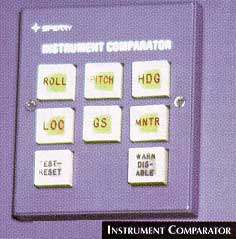
The Ground Proximity Warning System provides alert of possible terrain danger. Visual and aural warnings are provided under any of the following conditions:
When a warning occurs, smoothly pull up and apply engine thrust until the warning ceases. Climb at the maximum practical rate until the warning ceases or terrain clearance is assured. Determine the cause of the warning if possible.
F. INSTRUMENT COMPARATOR
An instrument comparator system as displayed in the Instrument Comparator figure (above, right) is designed to alert pilots to a disagreement between the captain's and copilot's instruments. When their instruments disagree by more than a pre-set amount, the appropriate button on the comparator illuminates to warn the pilots. For instance, if the heading (HDG) button illuminates, the pilots should check the compasses and determine which system is not reading correctly.
Send all comments to ![]() aeromaster@eng.fiu.edu
aeromaster@eng.fiu.edu
© 1995-98 ALLSTAR Network. All rights reserved worldwide.
| Funded in part by |
Updated: February 23, 1999