 |
|||||
| Home | Research | For Teachers | HISTORY Level 1 Level 2 Level 3 |
PRINCIPLES Level 1 Level 2 Level 3 |
CAREER Level 1 Level 2 Level 3 |
| Gallery | Hot Links | What's New! | |||
| Web Administration and Tools | |||||
|
|||||
| Home | Research | For Teachers | HISTORY Level 1 Level 2 Level 3 |
PRINCIPLES Level 1 Level 2 Level 3 |
CAREER Level 1 Level 2 Level 3 |
| Gallery | Hot Links | What's New! | |||
| Web Administration and Tools | |||||
Flight Instruments - Level 3
![]()
A. GENERAL
The magnetic compass was one of the first flight instruments. Even today, it is frequently the only direction-indicating instrument found in aircraft equipped only for VFR flight. The compass is a reliable, self-contained unit requiring no external power source. For this reason, it is extremely useful as a standby or emergency instrument. To use a magnetic compass satisfactorily, however, the pilot must understand certain principles of magnetism and the characteristics of a magnetic compass.
B. PRINCIPLES
A magnet attracts ferrous (iron) materials by producing an external magnetic field. The force of attraction is greatest at the poles of the magnet and least in the area halfway between the two poles. Lines of force flow from each of these poles, then bend around and flow toward the opposite pole, thus forming a magnetic field.
The earth is a huge magnet, with lines of force oriented approximately with the north and south magnetic poles. Because the aircraft compass is suspended to swing freely, it tends to align with the earth's magnetic lines of force.
The earth's magnetic poles are some distance from the geographic or "true" poles. The magnetic lines of force do not pass over the surface in a neat geometric pattern because they are influenced by the varying mineral content of the earth's crust. For these reasons, there is usually an angular difference, or variation, between true north and magnetic north from a given geographic location.
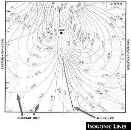
 Although this variation is not equal at all points on the
earth, it does follow a pattern. Points of equal variation can be connected by an isogonic
line, which can be plotted accurately on a chart (See Isogonic Lines
figure, right). In some places this variation is easterly; other places it is westerly.
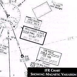
This variation is shown on sectional and IFR charts (See the IFR Chart
figure, left) using long dashed lines.
Although this variation is not equal at all points on the
earth, it does follow a pattern. Points of equal variation can be connected by an isogonic
line, which can be plotted accurately on a chart (See Isogonic Lines
figure, right). In some places this variation is easterly; other places it is westerly.
This variation is shown on sectional and IFR charts (See the IFR Chart
figure, left) using long dashed lines.
The pilot must understand the difference between true north and magnetic north
(called variation) because some of the directional values used in aviation are stated in
terms of magnetic north while others are stated in terms of true north. For example, the
direction finding instruments in the aircraft, including the magnetic compass, present
heading information in terms of magnetic north. All tracks, headings, and runways are
stated in terms of magnetic north. Maps, however, are constructed on true north. In
addition, wind direction is usually given in terms of true north, except surface wind
direction given by a control tower, which is stated in relationship to magnetic north.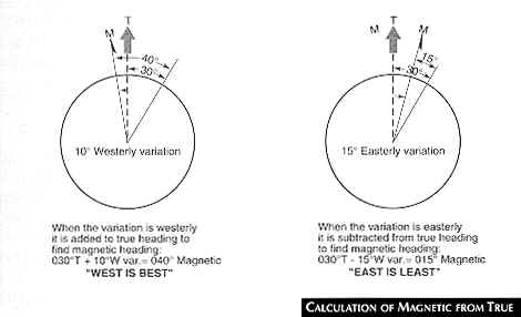
The pilot must use the variation to convert a direction expressed in terms of true north to magnetic north. To calculate magnetic azimuth, the pilot must subtract easterly variation or add westerly variation from the true azimuth (see Calculation of Magnetic from True figure, right). If the pilot wishes to convert a magnetic heading to a true heading, he or she must perform the opposite calculations.
C. MAGNETIC DIP
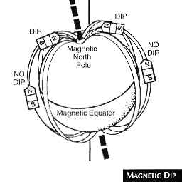 The lines of force in the earth's magnetic field pass through the
center of the earth, exit at both magnetic poles, and bend around to re-enter at the
opposite pole (see the Magnetic Dip figure, right). Near the Equator,
these lines become almost parallel to the surface of the earth. However, as they near the
poles, they tilt toward. the earth until in the immediate area of the magnetic poles they
dip rather sharply into the earth. Because the poles of a compass tend to align themselves
with the magnet lines of force, the magnet within the compass tends to tilt or dip toward
the earth in the same manner as the lines of force.
The lines of force in the earth's magnetic field pass through the
center of the earth, exit at both magnetic poles, and bend around to re-enter at the
opposite pole (see the Magnetic Dip figure, right). Near the Equator,
these lines become almost parallel to the surface of the earth. However, as they near the
poles, they tilt toward. the earth until in the immediate area of the magnetic poles they
dip rather sharply into the earth. Because the poles of a compass tend to align themselves
with the magnet lines of force, the magnet within the compass tends to tilt or dip toward
the earth in the same manner as the lines of force.
D. COMPASS CONSTRUCTION
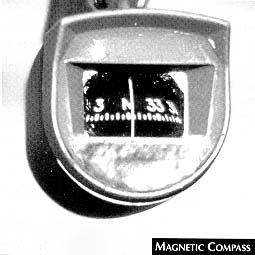
The aircraft's magnetic compass is a simple, self-contained instrument (See the Magnetic Compass figure, below right). It consists of a sealed outer case within, which is located, a pivot assembly and a float containing two or more magnets. A compass card is attached to the float with the cardinal headings (north, east, south and west) shown by corresponding letters. Between the cardinal headings, each 30° increment is shown as a number with the last zero removed. For example, 30° is shown as a numeral 3. The pilot may think of the compass card as a soup bowl turned upside down and balanced precisely on the point of a pencil. It rotates freely and can tilt up to 18°.
 The case is filled with an acid-free white kerosene that helps to
dampen oscillations of the float and lubricate the pivot assembly. The pivot assembly is
spring-mounted to further dampen aircraft vibrations so that the compass heading may be
read more easily. A glass face is mounted on one side of the compass case with a lubber,
or reference, line in the center. Compensating magnets are located within the case to
correct the compass reading for the effects of small magnetic fields generated by
components of the aircraft (refer to the next subsection).
The case is filled with an acid-free white kerosene that helps to
dampen oscillations of the float and lubricate the pivot assembly. The pivot assembly is
spring-mounted to further dampen aircraft vibrations so that the compass heading may be
read more easily. A glass face is mounted on one side of the compass case with a lubber,
or reference, line in the center. Compensating magnets are located within the case to
correct the compass reading for the effects of small magnetic fields generated by
components of the aircraft (refer to the next subsection).
E. COMPASS ERRORS
1. DEVIATION: The compass needle is affected when aircraft electrical equipment is operated and by the ferrous metallic components within the aircraft. These internal magnetic fields tend to deflect the compass from alignment with magnetic north. This tendency is called deviation. Deviation varies, depending upon which electrical components are in use.
The local magnetic field may also change as a result of mechanical jolts to the aircraft, from the installation of additional or different radio, equipment, or major mechanical work on an engine such as changing of the crankshaft or propeller. The crankshaft and the propeller are particularly susceptible to changes in inherent magnetism because they rotate in various magnetic fields.
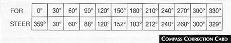
To reduce the effect of this deviation, the aircraft compass must be checked and compensated periodically by adjusting the compensating magnets. This procedure is called "swinging the compass". During compensation, the compass is checked at 30° increments. Adjustments are made at each of these points, and the difference between magnetic heading and compass heading is shown on a compass correction card (see the table Compass Correction Card, below). When flying compass headings, the pilot must refer to this card and make the appropriate adjustment for the desired heading. To preserve accuracy, the pilot must ensure that no metallic objects such as flashlights or sunglasses are placed near the compass because they may induce significant errors.
2. DIP ERROR: As previously mentioned, the compass card tends to align itself with the earth's magnetic field. At or near the Equator this causes little or no problem, but as the aircraft nears either of the magnetic poles, the dip error becomes significant.
In this manual, only dip errors in the Northern Hemisphere are described. (The errors are reversed in the Southern Hemisphere). Northerly turning error is the most important error (see the Northern Turning Error figure, below).
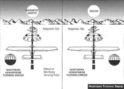
The compass card is mounted so that its center of gravity is well below the pivot point on the pedestal. When the aircraft is in a banked turn, the card also banks because of centrifugal force. While the card is in the banked attitude, the vertical component of the earth's magnetic field causes the compass to dip to the low side of the turn.
The error is most apparent when turning through headings close to north and south. When the aircraft makes a turn from a heading of north, the compass briefly indicates a turn in the opposite direction. When the aircraft makes a turn from a heading of south, the compass indicates a turn in the correct direction bur at a considerably faster rate than is actually occurring. Thus, when making a 360° right turn beginning at north, the compass card initially turns in the wrong direction; then, as the aircraft passes through east, the compass "catches up" with the actual heading. Passing through south, the compass leads the turn considerably. As the aircraft nose passes through west, the compass should approximate the correct heading. Then, as the aircraft nose approaches north again, the compass lags.
Pilots must understand that the northerly turning error occurs only while the aircraft is turning.
Acceleration error occurs during airspeed changes and is most apparent on headings of east and west. It is caused by a combination of inertia and magnetic dip. As the aircraft accelerates, the compass card, acting like a pendulum, tilts slightly during the acceleration because of the card's inertia.
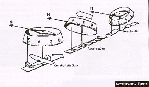 This momentary tilting displaces the compass card from its normal
alignment with magnetic north; therefore, when the aircraft accelerates in either an
easterly or westerly direction, the compass card momentarily indicates a turn toward the
north (see the Acceleration Error figure, right). The reverse is true
when the aircraft decelerates. If the aircraft decelerates on a beading of approximately
east or west, the pilots should remember the acronym ANDS: accelerate north,
decelerate south.
This momentary tilting displaces the compass card from its normal
alignment with magnetic north; therefore, when the aircraft accelerates in either an
easterly or westerly direction, the compass card momentarily indicates a turn toward the
north (see the Acceleration Error figure, right). The reverse is true
when the aircraft decelerates. If the aircraft decelerates on a beading of approximately
east or west, the pilots should remember the acronym ANDS: accelerate north,
decelerate south.
F. USE OF THE MAGNETIC COMPASS
It now should be evident why the magnetic compass is accurate only while the aircraft is flying wings-level in steady-state, non-accelerated flight. Turns using the magnetic compass can be accomplished best with the aid of the turn co-ordinator and the clock.
In a two-minute or standard-rate turn, as shown on the turn co-ordinator, the aircraft turns through 360° in two minutes, or 3°/sec. By dividing by three the number of degrees in the planned turn, the pilot may determine the number of seconds required in a standard-rate turn to accomplish the desired heading change. After rolling the aircraft out on the new heading, the pilot must wait a few seconds for the compass to settle down. Then he or she can check the new heading.
Send all comments to ![]() aeromaster@eng.fiu.edu
aeromaster@eng.fiu.edu
© 1995-98 ALLSTAR Network. All rights reserved worldwide.
| Funded in part by |
Updated: February 23, 1999