 |
|||||
| Home | Research | For Teachers | HISTORY Level 1 Level 2 Level 3 |
PRINCIPLES Level 1 Level 2 Level 3 |
CAREER Level 1 Level 2 Level 3 |
| Gallery | Hot Links | What's New! | |||
| Web Administration and Tools | |||||
|
|||||
| Home | Research | For Teachers | HISTORY Level 1 Level 2 Level 3 |
PRINCIPLES Level 1 Level 2 Level 3 |
CAREER Level 1 Level 2 Level 3 |
| Gallery | Hot Links | What's New! | |||
| Web Administration and Tools | |||||
Navigation Systems - Level 3
![]()
A. SYSTEM DESCRIPTION
The time-referenced scanning beam Microwave Landing System (MLS) has been adopted by ICAO as the standard precision approach system to replace ILS. MLS provides precision navigation guidance for alignment and descent of aircraft on approach to a landing by providing azimuth, elevation and distance. The system may be divided into five functions:
With the exception of DME, all MLS signals are transmitted on a single frequency through time sharing. Two hundred channels are available between 5031 and 5090.6 Megahertz (MHz). By transmitting a narrow beam which sweeps across the coverage area at a fixed scan rate, both azimuth and elevation may be calculated by an airborne receiver which measures the time interval between sweeps. For the pilot, the MLS presentation will be similar to ILS with the use of a standard CDI or multi-function display,
B. ILS LIMITATIONS
The Instrument Landing System (ILS) has served as the standard precision approach and landing aid for the last 40 years. During this time it has served well and has undergone a number of improvements to increase its performance and reliability. However, in relation to future aviation requirements, the ILS has a number of basic limitations:
C. MLS ADVANTAGES
As previously mentioned, ILS has limitations which prohibit or restrict its use in many circumstances. MLS not only eliminates these problems; but also offers many advantages over ILS including:
D. APPROACH AZIMUTH GUIDANCE
The approach azimuth antenna normally provides a lateral coverage of 40ş either side of the center of scan (see MLS Azimuth and Elevation Coverage figure, below). Coverage is reliable to a minimum of 20 NM from the runway threshold and to a height of 20,000 feet (ft). The antenna is normally located about 1000 feet beyond the end of the runway.
E. BACK AZIMUTH GUIDANCE
The back azimuth antenna provides lateral guidance for missed approach and departure navigation. The back azimuth transmitter is essentially the same as the approach azimuth transmitter. However, the equipment transmits at a somewhat lower data rate because the guidance accuracy requirements are not as stringent as for the landing approach. The equipment operates on the same frequency as the approach azimuth bur at a different time in the transmission sequence. On runways that have MLS approaches on both ends, the azimuth equipment can be switched in their operation from the approach azimuth to the back azimuth and vice versa. The MLS Azimuth and Elevation Coverage figure, below, shows MLS azimuth coverage volumes.
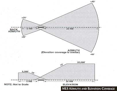
F. ELEVATION GUIDANCE
The elevation station transmits signals on the same frequency as the azimuth station. The elevation transmitter is normally located about 400 ft from the side of the runway between the threshold and the touchdown zone. The MLS Azimuth and Elevation Coverage figure, above, shows coverage volumes for the MLS elevation signal. It allows for a wide range of glide path angles selectable by the pilot.
G. RANGE GUIDANCE
Range guidance, consistent with the accuracy provided by the azimuth and elevation stations, is provided by the MLS precision DME (DME/P). DME/P has an accuracy of +100 ft as compared, with + 1200 ft accuracy of the standard. DME system. In the future it may be necessary to deploy DME/P with modes which could be incompatible with standard airborne DME receivers.
H. DATA COMMUNICATIONS
The azimuth ground station includes data transmission in its signal format which includes both basic and auxiliary data. Basic data may include approach azimuth track and minimum glide path angle. Auxiliary data may include additional approach information such as runway condition, wind-shear or weather.
Send all comments to ![]() aeromaster@eng.fiu.edu
aeromaster@eng.fiu.edu
© 1995-98 ALLSTAR Network. All rights reserved worldwide.
| Funded in part by |
Updated: February 23, 1999