 |
|||||
| Home | Research | For Teachers | HISTORY Level 1 Level 2 Level 3 |
PRINCIPLES Level 1 Level 2 Level 3 |
CAREER Level 1 Level 2 Level 3 |
| Gallery | Hot Links | What's New! | |||
| Web Administration and Tools | |||||
 |
|||||
| Home | Research | For Teachers | HISTORY Level 1 Level 2 Level 3 |
PRINCIPLES Level 1 Level 2 Level 3 |
CAREER Level 1 Level 2 Level 3 |
| Gallery | Hot Links | What's New! | |||
| Web Administration and Tools | |||||
![]()
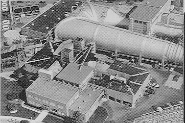
| One of the leading icing research resources in the United States is available at the NASA Lewis Research Center: the Icing Research Tunnel. |  |
 The
Icing Research Tunnel (IRT) is the world's largest refrigerated icing tunnel, capable of
duplicating the icing conditions encountered by aircraft by controlling liquid water
content (LWC), droplet size, and air temperature within the tunnel. The IRT is a
closed-loop atmospheric-type tunnel for tests of low-speed models. The test section is 6
ft high, 9 ft wide, and 20 ft long. Airspeed in the empty test section can be varied from
43.5 knots to 260.7 knots (50 to 300 mph). The IRT is scheduled for continuous testing
throughout the year. NASA Lewis is located in Cleveland, Ohio, adjacent to Cleveland
Hopkins International Airport. NASA Lewis is capable of providing complete security for
proprietary or Government classified test programs.
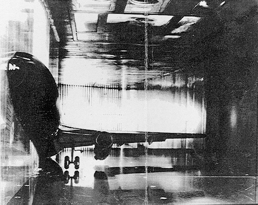
IRT facilities have been used in a number of ice protection
roles. Aircraft ground deicing/ anti-icing fluids were tested on a model of a Boeing
737-200 ADV.
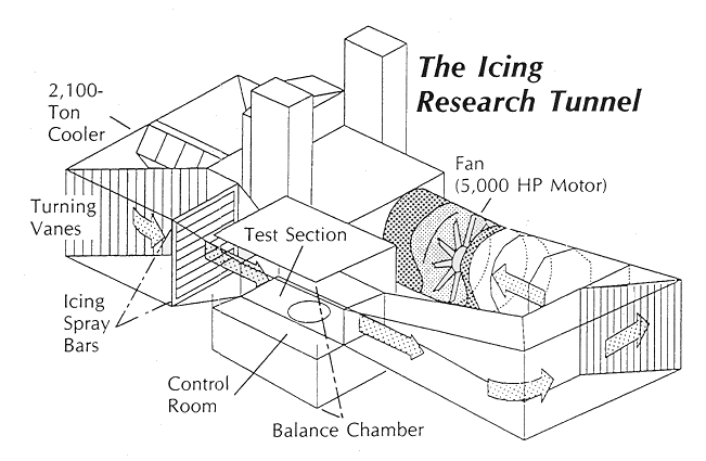
The maximum airspeed for an empty IRT test section is 260 knots (300 mph). Large model blockage (greater than 20 percent) significantly reduces test section maximum airspeed; for details, contact the IRT Facility Manager. The tunnel is operated at atmospheric pressure, and the air temperature range is controlled from ambient temperature to -20 degrees F +1 degree F. Tunnel temperature is determined by averaging several thermocouple measurements just downstream of the cooler.
The IRT uses a centralized exhaust system to simulate airflow for inlet models. The flow rate can be varied from 3 to 80 lbm/sec (pound mass per second).
A 25-ft diameter, 12-bladed, fixed-pitch fan of laminated Sitka spruce provides the airflow. The fan is directly coupled to an electric motor in a faired nacelle. The 5,000 hp electric motor controls the fan speed to an accuracy of ~ 0.5 rpm over the fan's range of 50 to 460 rpm. Fan acceleration rates of between 1 and 10 rpm/(sec squared) are available to simulate aircraft flight profiles. The acceleration is not the normal mode of operation and such use must be prearranged and approved.
The test section is 6 ft high, 9 ft wide, and 20 ft long. The center of the 8.6-ft diameter test section turntable is 11.5 ft from the inlet of the test section. The turntable rotates +20 degrees horizontally. Model mounting details and bolt patterns are available upon request. Lift and drag can be measured using a balance. Just drag can be measured using a traversing wake survey probe.
The test section ceiling hatch, used for model installation, is 4 ft wide by 12 ft long. The hatch contains several remov able panels, which can be used to mount equipment, or the panels can be replaced with Lucite windows for lighting or photographic work.
There are four viewing windows between the control room and the test section. The three electrically heated windows are 2.5 ft wide by 3.75 ft high. The unheated window is 2 ft wide by 1 ft high.
A large enclosure (the balance chamber) surrounds the test section and control room and shares the same static pressure as the test section so that instrumentation leads and service lines can enter the tunnel test section ceiling or floor without a pressure bulkhead or hermetically sealed connections.
Eight sprays bars containing air-blast nozzles are used to develop a uniform test section icing cloud environ ment approximately 3 ft high by 4 ft wide. The LWC varies by no more than +10 percent within the test region. The nozzles produce water droplets of mean volumetric diameters (MVD's) between 15 and 40 microns with LWC from 0.5 to 2.5 gm/m3. Two nozzle sizes are available: standard and mod-1. In general, the mod-1 nozzles provide lower LWC. Specific cloud calibrations are available upon request.
The IRT building is connected to the tunnel's balance chamber by an air-lock chamber and a 10- x 10-ft model access door. Space for model buildup is avail able in the shop area.
The balance chamber is a three-story structure. A retractable access door is located at
the side of the balance chamber and has an opening 9 ft wide by 8 ft high between the shop
area and the balance chamber. The second floor of the balance chamber includes the tunnel
test section, the tunnel personnel access doorway, and the facility control room. The test
section model access hatch and the test section altitude exhaust duct are located on the
third floor.
The control room is on the second floor of the balance chamber. Approximately half of the control room is occupied by facility controls and the Lewis in-facility data acquisition system (ESCORT). The remainder of the control room is available for user-supplied equipment.
The IRT is operated by an interactive computer control system. For example, the system controls fan speed (airspeed), air temperature, spray bar air and water pressures, spray duration, turntable position, tunnel lighting, and emergency shutdown.
Data can be monitored and recorded by both an in facility computer and a data-linked remote mainframe. The ESCORT steady-state data system can be expanded to record more than 500 data channels and all of the data can be permanently recorded on a data collector for further off-line processing. As presently configured, the ESCORT system can record 192 analog inputs (i.e., temperature, pressure, position). Of these inputs, 92 are reserved for facility systems monitoring and 100 are available for user designated parameters. In addition, as part of ESCORT, an electrically scanned pressure measuring system (ESP) provides an additional 128 channels for user-defined pressure measurements. Two ESP pressure ranges are available, 5 or 15 psid, and have an accuracy of +0.1 percent of full scale.
Video and still photographic equipment may be used for recording visual data and documentation. Side view photos may be taken from the control room, or top views through the model access hatch windows. Camera system components available include video cameras with zoom lenses, monitors, and VHS tape recorders. A high-speed video system capable of 1,000-frame/sec exposure is also available. In most instances users should provide still camera equipment, film, and videotapes.
Several power systems are available to the tunnel user. These systems are as follows:
| 440 V | 60 Hz | 400 A | 3-phase |
| 208 V | 60 Hz | 225 A | 3-phase |
| (This system can be used as single-phase 208V or as a single-phase 110V.) | |||
| 115 V | 400 Hz | 175 A | 3-phase |
| (440 V, 60 Hz converted to 115 V, 400 Hz) | |||
| 115 V | 60 Hz | 250 A | 1-phase |
| 115 V | 400 Hz | 30 A | 1-phase |
| 26 V | 400 Hz | 15 A | 1-phase |
| 28 Vdc | 250 A | ||
| (440 V, 60 Hz to 28 Vdc invertor) | |||
| 28 Vdc | 25 A | ||
A 3/4 ton-diameter line provides steam at 40 psig for model and/or instrumentation deicing.
A gas burner outside the IRT provides heated air to the model from 100 to 700 degrees F. In addition, an electric heater can be used to increase the air temperature to 900 degrees F. The maximum flow rate of the heated air is 1 lbm/sec at 120 psi". Service or shop air nominally at 125 psig is available for the model if required.
Tunnel users must perform a detailed stress analysis on their model and support systems and provide it to the IRT Facility Manager. A series of aerodynamic tests must be performed in the IRT on the model prior to icing tests. These tests will be conducted by IRT personnel who will approve the model for icing tests if it performs satisfactorily.
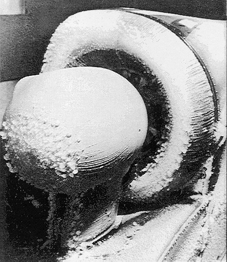
The IRT's large test section allows some full-sized component ice protection experiments, such as the inlet pictured above.
The tunnel time charged to users includes the total time that the facility is available to the tunnel user. This time includes model and instrumentation installation and removal (including crating for shipment), experiment time, and the time required to return the tunnel and associated area to its pretest condition. Crating and shipping both to and from the IRT is the responsibility of the user.
The occupancy charge to use the facility is set by LeRC and is reviewed on a case-by-case basis and varies depending on services, equipment, and supplies necessary to perform the test. There are four basic types of working agreements
NASA Test Program
NASA/lndustry Cooperative Program (Nonreimburs able Space Act Agreement)
Other U.S. Government Agency Program (Reimburs able or Nonreimbursable Interagency Agreement)
Industry Proprietary or Noncooperative Program (Re imbursable Space Act Agreement)
In most instances, tunnel users should be prepared to provide necessary technicians, mechanics, tools, spare parts, special equipment, and supplies to perform model installation in the tunnel. In some circumstances these NASA LeRC resources may be used at a charge to the customer.
![]()
The following information was extracted from a pamphlet provided by the NASA Lewis Research Center's IRT facility. Detailed information on user requirements may be obtained by contacting the IRT facility manager directly at
The IRT Facility Manager
NASA Lewis Research Center
21000 Brookpark Road
Cleveland, Ohio 44135
216 433-4000
Send all comments to ![]() aeromaster@eng.fiu.edu
aeromaster@eng.fiu.edu
© 1995-98 ALLSTAR Network. All rights reserved worldwide.
Updated: February 23, 1999