 |
|||||
| Home | Research | For Teachers | HISTORY Level 1 Level 2 Level 3 |
PRINCIPLES Level 1 Level 2 Level 3 |
CAREER Level 1 Level 2 Level 3 |
| Gallery | Hot Links | What's New! | |||
| Web Administration and Tools | |||||
 |
|||||
| Home | Research | For Teachers | HISTORY Level 1 Level 2 Level 3 |
PRINCIPLES Level 1 Level 2 Level 3 |
CAREER Level 1 Level 2 Level 3 |
| Gallery | Hot Links | What's New! | |||
| Web Administration and Tools | |||||
![]()
Pressure boosters are rarely used in aircraft (almost all planes use de-boosters). If we need higher pressure, we must change the ENTIRE power and actuating system. This adds weight that is not needed. In general, we cannot put in larger pistons and piston cylinders to increase the power, because, normally, we don’t have the room for it. A simple solution is to raise the pressure in a LOCALIZED area.
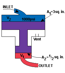
The function of a pressure booster is to act like a transformer--that is, it raises the pressure of a small circuit connected to the power system. The booster is a cylinder made up of two pistons of different surface areas that are connected. The larger surface area (A1) is connected to the inlet side of the hydraulic system, and, the smaller surface area (A2) is connected to the outlet side of the hydraulic system


Example:
Suppose that the actuating cylinder (used to move the control surface) normally gets
hydraulic fluid at a pressure of
p = 1000 psi and that this pressure would act on a piston surface area A = 10 square
inches. The total force developed F would be p times A or 10,000 lb. But, suppose we need
a force of 60,000 lb to move the control surface... So we add a booster.
If the inlet side area A1 is 3 square inches, then the force, F, developed by the hydraulic fluid is
![]()
Since the pistons of the booster are connected (purple in the diagram above), and we assume that they have negligible inertia, then the force developed on the smaller piston is the same as the force on the larger piston. If the outlet side area A2 is 1/2 square inch, then the pressure developed on the outlet side would be
![]()
At the actuating cylinder the force developed would be the pressure times the area of the actuating cylinder or
(6000 lb/sq. in.) x (10 sq. in.) = 60,000 lb
as required.
Disadvantages of a Pressure Booster
If a 3 inch piston stroke is needed from the actuating cylinder moving the control surface, then the total volume of fluid moved by the actuating piston's movement is stroke x piston area = (3 inches) x (10 square inches) = 30 cubic inches
This is the volume of fluid that must move out of the booster to the actuating cylinder. Thus the smaller piston in the booster must stroke a distance equal to the volume of fluid needed divided by the piston area = (30 cu. in.) / (1/2 sq. in.) = 60 inches = 5 feet!
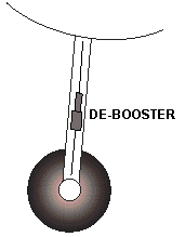
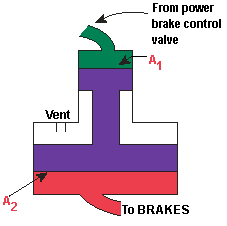
Pressure deboosters are used to reduce the pressure in the system to a level that can be used by certain devices. Pressure deboosters are pressure boosters turned upside down (that is, the inlet side of the booster has the smaller area piston and the outlet side has the larger area piston). They are employed in power brake systems, using engine power to help apply the brakes. Since aircraft wheels are made of magnesium, any high pressure on the wheels will cause them to split. That is why they must de-boost the pressure gotten from engine.
The inlet line to the debooster comes from the power brake control valve. The outlet line goes to the brake system. This valve meters hydraulic fluid and hydraulic pressure directly. The force applied to the wheels to make them stop is proportional to how hard you push on the rudder pedal. It is normally used for a 1 or 2 cubic inch application.


Hydraulic fluids that have been used are of several types: water-based, mineral-based and synthetic type oils. Each has its advantages and disadvantages. Though several types are listed here, newer types of oils are being developed.
Caution: Never use a vegetable-base oil. At high temperatures, vegetable-based oils form a residue which is gummy and can clog the hydraulic system, which can lead to catastrophic results.
Send all comments to ![]() aeromaster@eng.fiu.edu
aeromaster@eng.fiu.edu
© 1995-98 ALLSTAR Network. All rights reserved worldwide.
Updated: February 17, 1999