 |
|||||
| Home | Research | For Teachers | HISTORY Level 1 Level 2 Level 3 |
PRINCIPLES Level 1 Level 2 Level 3 |
CAREER Level 1 Level 2 Level 3 |
| Gallery | Hot Links | What's New! | |||
| Web Administration and Tools | |||||
|
|||||
| Home | Research | For Teachers | HISTORY Level 1 Level 2 Level 3 |
PRINCIPLES Level 1 Level 2 Level 3 |
CAREER Level 1 Level 2 Level 3 |
| Gallery | Hot Links | What's New! | |||
| Web Administration and Tools | |||||
![]()
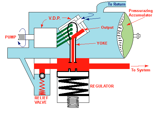
The pump shown in the diagram was used in the late 60s and 70s. It may still be used in aircraft of that era. The pump works in this manner: The accumulator always keeps a pressure in the self-contained reservoir. Let’s say that the hydraulic system has finished actuation. As the pressure builds up, the pressure felt in the area around the selector valve is felt at the regulator piston. As the pressure builds up, the fluid pressure on the regulator piston will be higher than the spring force, causing the piston to move downward. As the piston moves down, the yoke will pull the piston chamber in the pump down, decreasing the pump angle and causing a decrease in the volumetric output of pump. As the actuation starts again, the pressure decreases, making the piston move upward (fluid pressure force being less than the spring force) and moves the yoke upward, increasing the pump angle and the volumetric output. The relief valve to the left of the regulator acts in same fashion as that of old systems (it opens a path to the accumulator if the pressure in the system is higher than the allowable range of operating pressures in the hydraulic system).
Such a system has not been used in aircraft since 1945. However, since that time, it has been used in power steering systems of cars.
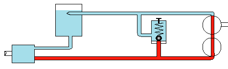
This type of system was used in simple aircraft. The selector valve used in this kind of system was an open center selector valve which allowed fluid to pass through the selector valve continuously, but directed fluid flow to other flow routes by movement of the selector valve. The route the fluid took depended upon the pilot and the task to be accomplished (for example: moving flaps, or ailerons). When the task was complete, the pushing action of the hydraulic fluid on the piston in the selector valve would cause the pressure to build in the system. Therefore, it was necessary to put the selector valve in "neutral" when the task was complete. When the selector valve is placed in neutral, the fluid pressure is the same as the return line pressure.
Caution: Use 1 open center selector valve at a time, always returning it to neutral. Never use 2 selector valves simultaneously as you can damage the hydraulic system.
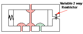
To automate the selector valve's return to the neutral position, you can use either a pressure control sensor or a time delay (spring and adjustable restrictor) whereby the pressure on the piston will move the piston back to the center.
Send all comments to ![]() aeromaster@eng.fiu.edu
aeromaster@eng.fiu.edu
© 1995-98 ALLSTAR Network. All rights reserved worldwide.
| Funded in part by |
Updated: February 17, 1999