 |
|||||
| Home | Research | For Teachers | HISTORY Level 1 Level 2 Level 3 |
PRINCIPLES Level 1 Level 2 Level 3 |
CAREER Level 1 Level 2 Level 3 |
| Gallery | Hot Links | What's New! | |||
| Web Administration and Tools | |||||
 |
|||||
| Home | Research | For Teachers | HISTORY Level 1 Level 2 Level 3 |
PRINCIPLES Level 1 Level 2 Level 3 |
CAREER Level 1 Level 2 Level 3 |
| Gallery | Hot Links | What's New! | |||
| Web Administration and Tools | |||||
![]()
Examples of where automatic hydraulic transmission may be employed will be discussed.
Let us say we want to operate the radar on a jet aircraft. Suppose the radar itself is
being operated by an alternator and the alternator frequency (number of cycles per second)
depends on the RPM of the engine running the alternator. The RPM of the engine may change
due to operational requirements, while we want a steady number of cycles coming out of the
alternator to run the radar.
Let us take a hypothetical case of a turbojet aircraft. At take-off, the jet is
"revving" at 12,000 RPM, at cruising altitude the jet runs at 6,000 RPM and when
landing the jet runs at 3,000 RPM. Let’s say we want the alternator to work
constantly at 6,000 cycles. This is what we do.

As the speed of the turbine increases because of take-off, the alternator cycles also
increase. Sensing the increase, the constant speed drive "tells" the yoke on the
variable displacement pump of the automatic hydraulic transmission (see section 1.19 - Hydraulic motors) to decrease the pump angle, thereby decreasing the
volumetric output of the pump. This, in turn, will decrease the speed of the hydraulic
motor that runs the alternator, therefore, decreasing the cycle speed of the alternator.
As the turbine decreases its rotational speed when the aircraft reaches its cruising
altitude, the constant speed drive senses the decrease and it "tells" the yoke
on the variable displacement pump to increase the pump angle to offset the decrease in
speed of the jet engine. The increased pump angle will increase the volumetric
displacement of the pump as well as the speed of the hydraulic motor that runs the
alternator, thereby increasing the cycle speed of the alternator.
At landing, the engine speed decreases further so that the aircraft can lose lift and
land. Again, the constant speed drive, sensing the decrease in engine speed,
"tells" the yoke on the variable displacement pump to increase angle to offset
the decrease in engine speed. The increase in pump angle increases volumetric
displacement, causing an increase in speed of the hydraulic motor that runs the alternator
and, in turn, causes the cycle speed of the alternator to increase.
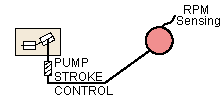
The constant speed sensing device could be connected to a pump stroke control. The pump stroke control replaces the yoke as the means of increasing or decreasing the angle of the variable displacement pump.

The hydraulic motor and variable displacement pump can be used separately, as is shown on the diagram below. The pump can be connected to the engine and the motor to the alternator. As one pump decreases its angle, the motor is made to increases its angle, increasing the torque generated to the alternator. As one pump increases its angle, the motor is made to decrease its angle, decreasing the torque and increasing the RPM to the alternator.

With this set-up, we can get any variation of torque and speed (RPM).
Send all comments to ![]() aeromaster@eng.fiu.edu
aeromaster@eng.fiu.edu
© 1995-98 ALLSTAR Network. All rights reserved worldwide.
Updated: February 17, 1999