|
|||||
| Home | Research | For Teachers | HISTORY Level 1 Level 2 Level 3 |
PRINCIPLES Level 1 Level 2 Level 3 |
CAREER Level 1 Level 2 Level 3 |
| Gallery | Hot Links | What's New! | |||
| Web Administration and Tools | |||||
|
|||||
| Home | Research | For Teachers | HISTORY Level 1 Level 2 Level 3 |
PRINCIPLES Level 1 Level 2 Level 3 |
CAREER Level 1 Level 2 Level 3 |
| Gallery | Hot Links | What's New! | |||
| Web Administration and Tools | |||||
![]()
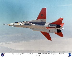
During aircraft turns or maneuvers, if wing air loads on one wing are greater than loads on the other wing, and, we attempt to sweep the wings back or sweep them forward, these motions will occur so unevenly that probable loss of aircraft and pilot will result. Therefore, if we want to synchronize our sweepback motion, we must use devices called flow equalizers.
Another example where flow equalizers are needed is in case of air-to-air
missile attack. Suppose our selector valve is set to neutral and we try to get away from a
rocket missile by turning right or left. The pressure forces on the wings would be so
unequal that the wing actuating cylinder (of the wing undergoing the smaller turn radius)
would act as a pump, since its greater pressure loading would cause wing sweepback. The
hydraulic fluid would be pushed out of one cylinder and the only path that it could take
would be to the other wing's actuating cylinder, causing that cylinder’s wing to go
in the opposite direction to that of the first wing. This would be catastrophic.
If a downward force is applied to the left piston and the selector valve is closed, the oil is forced into the right cylinder causing the right piston to move up--a motion opposite to what is needed.
A device that may be used as a flow equalizer is a power pump that is run in reverse. If the power pump direction were reversed, the flow would push on the outer teeth of the gear and not on the meshing teeth at the center because the oil can’t be compressed. Since fluid moves towards the meshed teeth at the center of the pump (A1), as well towards teeth closest to pump casing (A2), and since the fluid pressure acts on twice the teeth area (A2) than at A1, the gear direction reverses, as compared to the direction of operation of a power pump.
|
Thus the flow equalizer is made up of two power pumps placed side by side in which the drive gears of both pumps are connected (see the side view for the figure below). The main figure (the one in red) shows the two power pumps of the side view, cut along the side view's centerline and opened like a book. When one drive gear turns (2), it causes the other to turn as well (1) through the connection (the blue shaft). Since the volumetric output per revolution is the same for both sides, we have found the right device to keep synchronization.
 |
 |
This kind of power pump is set between the two cylinders requiring equalization and would channel the flow to both cylinders (as shown below left). The VICKERS EQUALIZER setup is shown below right, where the VICKERS pumps are connected by a shaft at the center of the diagram. Input is at the top of the pumps and outputs are shown by the red arrows (see Section 1.08--System Power Pumps).
 |
 |
You should never connect the actuation cylinders of the two wings is series, since this type of circuit, for it to work, would require cylinder (1) to put out twice the fluid pressure, or even more, in order to operate itself and cylinder (2) [see the figure below). The hydraulic fluid in this series type of circuit will burst the hydraulic tubing, due to the fluid pressures required to operate both actuating cylinders, and, because this type of circuit does not compensate for expansion or contraction of the hydraulic fluid. The tubing between cylinders and to the selector valve are colored both blue and red because they can transmit high pressure hydraulic fluid as well as return line pressure hydraulic fluid.
These circuits are used to cause certain operations to occur in a particular sequence. Sequencing circuits have been used, for example, for the complete ejection of a pilot from the plane. The sequencing valve is such that it sends hydraulic fluid through the valve to the other sequencing valves and actuating cylinders. As the piston rod (of the extreme left cylinder) moves upward, it activates the sequencing valve releasing hydraulic fluid to the next cylinder.
As the actuating cylinder piston moves upward, it hits the rod of the sequencing valve (shown in green). The rod, in turn, moves up into the sequencing valve pushing the poppet up and releases the hydraulic fluid from the holding side (blue side) to the releasing side (red side), permitting it to go to the next cylinder and sequencing valve.
In the diagram below, the system is set so that the sequence of actuation is 2,4,3,1.
We can design a system so that it can perform a double sequence of actuations. In the diagram below, the system is set so that when the selector valve is open to the "red" side, the sequence of events from left to right is 1,3,4,2 (cylinder numbers in red). When the selector valve is open to the "blue" side, the sequence of events goes from right to left and is 4,3,1,2.
By proper connection of the sequencing valves and actuating cylinders, any sequence of events can be made to occur.
Send all comments to ![]() aeromaster@eng.fiu.edu
aeromaster@eng.fiu.edu
© 1995-98 ALLSTAR Network. All rights reserved worldwide.
| Funded in part by |
Updated: February 17, 1999