 |
|||||
| Home | Research | For Teachers | HISTORY Level 1 Level 2 Level 3 |
PRINCIPLES Level 1 Level 2 Level 3 |
CAREER Level 1 Level 2 Level 3 |
| Gallery | Hot Links | What's New! | |||
| Web Administration and Tools | |||||
|
|||||
| Home | Research | For Teachers | HISTORY Level 1 Level 2 Level 3 |
PRINCIPLES Level 1 Level 2 Level 3 |
CAREER Level 1 Level 2 Level 3 |
| Gallery | Hot Links | What's New! | |||
| Web Administration and Tools | |||||
![]()
Selector valves are used as (1) directional control devices to insure the movement of the hydraulic fluid flow in the proper direction, and (2) as stop-locks to lock the selector switch in a certain position.
There are three types of selector valves. They are rotary type, piston type and poppet type.
Rotary types
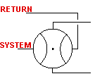
Rotary type selector valves are plugs within which are passage ways for the fluid to move through. Tubing from the hydraulic pump or return line are connected to the rest of the hydraulic system by movement of the plug. You cannot use high pressure oil because of leakage around the plug. To reduce leakage, you might want to make the plug fit more tightly into the selector valve body. However, the better you make the fit, the more friction will exist between the plug and the selector valve body, making it difficult to operate.
 |
 |
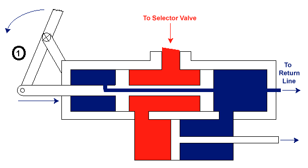
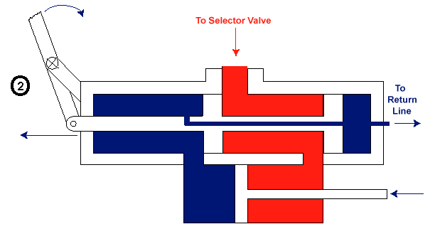
Piston Type
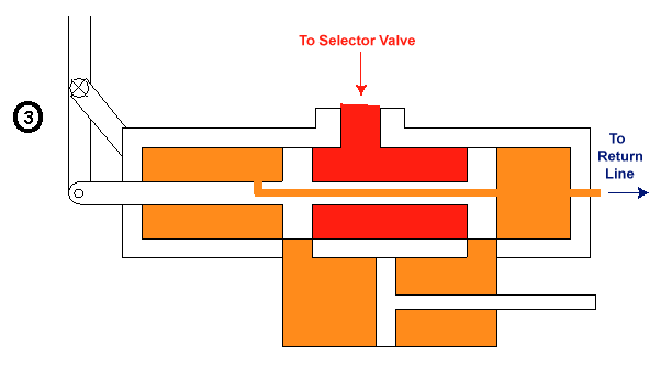
Positions 1, 2 and 3 (shown below) are representative positions for the piston-type selector valve. Position (1) is the position of the selector valve, for example, upon the extension of the landing gear or the lowering of flaps. Position (2) is the position of the selector valve upon retraction of the landing gear or the raising of the flaps. Position (3) is the stop-locking position of this type of valve. This piston type valve uses the Vickers spool mechanism in which the piston "lands" isolate the high pressure oil (red area) from the low pressure oil (blue area).
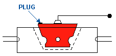
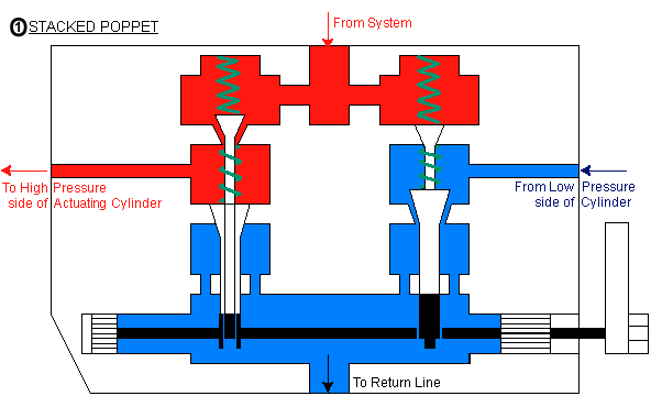
Poppet Type - Stacked Poppet
In this type valve, any movement of the handle (at the lower right of the diagram) changes the camshaft and cam settings, thereby opening and closing the poppet valves and letting high and low pressure oil to the proper sides of the actuating cylinder and return line, respectively.
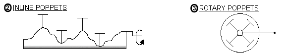
In in-line poppets, the poppet valves are set up along a cam shaft, in the same manner as for the intake and exhaust valves of a car engine. The camshaft is represented by the "sinusoidal" line in the diagram below. However, the motion of the poppets are controlled by the pilot.
These mechanical type selector valves require a fair amount of tubing. In order to reduce the amount of tubing, electric switches have been used to operate solenoids which operate the selector valves. This has the added advantage of reducing the wasteful motions of pilot. This is type of combined electronic circuits and hydraulic system is called electrohydraulics.
Send all comments to ![]() aeromaster@eng.fiu.edu
aeromaster@eng.fiu.edu
© 1995-98 ALLSTAR Network. All rights reserved worldwide.
| Funded in part by |
Updated: February 23, 1999