 |
|||||
| Home | Research | For Teachers | HISTORY Level 1 Level 2 Level 3 |
PRINCIPLES Level 1 Level 2 Level 3 |
CAREER Level 1 Level 2 Level 3 |
| Gallery | Hot Links | What's New! | |||
| Web Administration and Tools | |||||
 |
|||||
| Home | Research | For Teachers | HISTORY Level 1 Level 2 Level 3 |
PRINCIPLES Level 1 Level 2 Level 3 |
CAREER Level 1 Level 2 Level 3 |
| Gallery | Hot Links | What's New! | |||
| Web Administration and Tools | |||||
![]()
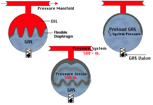
At the bottom of the accumulator is a gas valve. Compressed gas at about one half the system pressure is let into the accumulator through the gas valve. This forces the diaphragm that separates the oil side from the gas side to "pop" up towards the oil side. Then oil is sent through the system. When the system pressure reaches a point when it is greater than the pressure of the accumulator, the diaphram will deploy (inflate). Using Boyle’s Law, the compressed gas will increase in pressure as its volume decreases. The diaphragm will move up or down, depending on system pressure.

When the diaphragm is at half way, the gas volume will be ½ as much as it was initially, while the acculator pressure will be twice as much as its pre-load pressure (i.e., 1/2 system pressure). Therefore when the accumulator is at half volume of gas, it will be charged at full system pressure.
In a confined gas at constant temperature, the pressure is inversely proportional to its volume--that is, a gas with initial pressure P1 and volume V1 will have new pressure P2 and volume V2 such that P1V1 = P2V2. The product PV equals nRT, the product of n, the number of moles of the gas; R, the universal gas constant; and, T the temperature. Thus, for constant temperature, the product nRT is a constant.
The preload is checked every day. Nitrogen and helium are preferred to compressed air. Oxygen leaks into the oil will cause spontaneous combustion and that is why it is not used in the accumulator. Carbon dioxide (CO2 ) is not used because it liquefies at 800 or 900 psi (which is considered low pressure compared to the pressure requirements of the system).
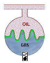
A. Spherical Type
The accumulator has to withstand about 450,000 lb of force. The spherical shape is used because a monocoque (single shell) body is the strongest and can withstand high pressures before failing.

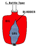
B. Bottle Type
This shape is not used because of bladder which expands and contracts

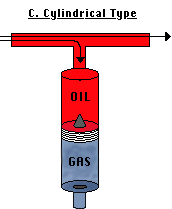
C. Cylindrical Type
This type is not used very often because friction will cause the wearing of both wall and piston, thereby allowing the gas pressure to escape. Oil and gas blowby (bypassing of piston by high pressure gas and oil) can occur.

Send all comments to ![]() aeromaster@eng.fiu.edu
aeromaster@eng.fiu.edu
© 1995-98 ALLSTAR Network. All rights reserved worldwide.
Updated: February 17, 1999