Section 1.5 - Aircraft Hydraulic System Reservoir Design

Functions of the Reservoir
- Provides air space for expansion of the oil due to temperature changes
- Holds a reserve supply of oil to account for
- thermal contraction of oil.
- normal leakage - oil is used to lubricate piston rods and cylinder seals. When the
piston rod moves, it is scraped to remove impurities that might collect on the rod when
returning into actuating cylinders. If many actuating cylinders are operating at the same
time, then the amount of oil lost is greater.
- emergency supply of oil - this case occurs only when the hand pump is used.
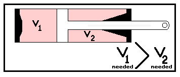
- volume changes due to operational requirements - oil needed on side 2 of piston head is
less than that needed on side 1 of cylinder piston (which occurs during actuation).
- Provides a place to remove air or foam from liquid.
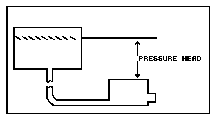
- Provide a pressure head on the pump, that is, a pressure head due to gravity and depends
upon the distance of the reservoir above the power pump.
Construction of Reservoir
In the construction of a reservoir, one must know:
- Material: for the reservoir itself 5052 aluminum has been used. It is weldable and
ductile, it can work in the needed temperature range and it must work when it is in any
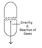
position and orientation to the earth (example: 1. In space, it is on its side; gravity is
pulling on the reservoir's "sides"; 2. during blast-off, gravity is forcing the
liquid to the tank's bottom.)

Example 1. |
Example 2. |
- Size: To obtain the size of the reservoir needed, one must calculate the volume of oil
needed for one emergency actuation. This means finding the amount of oil needed for all
emergency equipment to work. Then, it is necessary to calculate the volume for thermal
contraction by taking all oil volumes of the hydraulic system, finding the coefficient of
contraction and multiplying it by the number of degrees in the temperature range expected
during operation. You must do the same for all oil volumes in operational requirements,
thermal expansion, leakage, etc.
- Shape: You must look at the space available to fit the tank. A sphere is the best
shape to use because uniform stresses are generated by the interior pressure. Its one
major disadvantage is that it is difficult to mount. The next best shape is a domed
cylindrical shape. Not only can it be mounted easily, but it can be made to order.
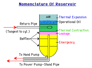 A
stand pipe to the power pump is needed and is always in the middle of the tank.
Regardless of variation in its orientation (upright or on its side), it will be submerged.
The return pipe from the rest of the hydraulic system is put near the top of liquid in the
tank, at a tangent to the tank surface, so that the fluid entering releases all its energy
through swirling at the top and dissipates it through release of bubbles of
foam.
Baffles within the tank are used for two reasons:
- they strengthen the tank against pressure from within and outside of the tank, and, more
importantly,
- they are used to stop the swirling effect of the return oil from producing a whirlpool.
This effect would only make the stand pipe in the center of the tank suck in the column of
air.
Filler pipe. Such a pipe eases the replenishing of the reservoir liquid. Since
liquid seeks its own level, we put the filler pipe so that its mouth has the same
level as the design level in the reservoir.
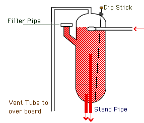 Vent
to atmosphere- Initially, vents were introduced because a vent will not allow a void to
form within the tank. However, as ceiling altitudes increased, pressure within the tank
and the hydraulic system was being lost and cavitation occurred. To stop this
phenomenon from happening, pressurized reservoirs were created (see section 1.7).
Dipstick-Sometimes filler pipes could not be used to add oil and tanks would have to be
filled from the top. This made it difficult to measure the oil. The dipstick was
therefore introduced. A long stick with marks on it, its job was to measure oil depth.
Send all comments to  aeromaster@eng.fiu.edu
© 1995-98 ALLSTAR Network. All rights reserved worldwide.
| Funded in part by |
 |
Updated: February 23, 1999


![]()


 A
stand pipe to the power pump is needed and is always in the middle of the tank.
Regardless of variation in its orientation (upright or on its side), it will be submerged.
The return pipe from the rest of the hydraulic system is put near the top of liquid in the
tank, at a tangent to the tank surface, so that the fluid entering releases all its energy
through swirling at the top and dissipates it through release of bubbles of
  Vent
to atmosphere- Initially, vents were introduced because a vent will not allow a void to
form within the tank. However, as ceiling altitudes increased, pressure within the tank
and the hydraulic system was being lost and cavitation occurred. To stop this
phenomenon from happening, pressurized reservoirs were created (see section 1.7).
Vent
to atmosphere- Initially, vents were introduced because a vent will not allow a void to
form within the tank. However, as ceiling altitudes increased, pressure within the tank
and the hydraulic system was being lost and cavitation occurred. To stop this
phenomenon from happening, pressurized reservoirs were created (see section 1.7).![]() aeromaster@eng.fiu.edu
aeromaster@eng.fiu.edu