 |
|||||
| Home | Research | For Teachers | HISTORY Level 1 Level 2 Level 3 |
PRINCIPLES Level 1 Level 2 Level 3 |
CAREER Level 1 Level 2 Level 3 |
| Gallery | Hot Links | What's New! | |||
| Web Administration and Tools | |||||
|
|||||
| Home | Research | For Teachers | HISTORY Level 1 Level 2 Level 3 |
PRINCIPLES Level 1 Level 2 Level 3 |
CAREER Level 1 Level 2 Level 3 |
| Gallery | Hot Links | What's New! | |||
| Web Administration and Tools | |||||
Flight Instruments - Level 3
![]()
A. GENERAL
The gyro instruments include the heading indicator, attitude indicator and turn coordinator (or turn-and-slip indicator). Each contains a gyro rotor driven by air or electricity and each makes use of the gyroscopic principles to display the attitude of the aircraft. It is important that instrument pilots understand the gyro instruments and the principles governing their operation.
B. PRINCIPLES
1. RIGIDITY IN SPACE: The primary trait of a rotating gyro rotor is rigidity in space, or gyroscopic inertia. Newton's First Law states in part: "A body in motion tends to move in a constant speed and direction unless disturbed by some external force". The spinning rotor inside a gyro instrument maintains a constant attitude in space as long as no outside forces change its motion. This stability increases if the rotor has great mass and speed. Thus, the gyros in aircraft instruments are constructed of heavy materials and designed to spin rapidly (approximately 15,000 rpm for the attitude indicator and 10,000 rpm for the beading indicator).
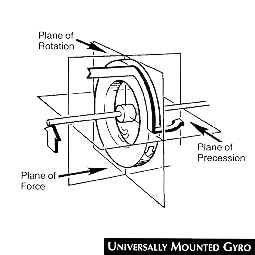
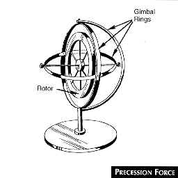
2. PRECESSION: Another characteristic of gyros is precession, which is the tilting or turning of the gyro axis as a result of applied forces. When a deflective force is applied to the rim of a stationary gyro rotor, the rotor moves in the direction of the force. When the rotor is spinning, however, the same forces causes the rotor to move in a different direction, as though the force had been applied to a point 90° around the rim in the direction of rotation (See the Precession Force figure, below right). This turning movement, or precession, places the rotor in a new plane of rotation, parallel to the applied force.
Unavoidable precession is caused by aircraft maneuvering and by the internal friction of attitude and directional gyros. This causes slow "drifting" and thus erroneous readings. When deflective forces are too strong or are applied very rapidly, most older gyro rotors topple over, rather than merely precess. This is called "tumbling" or "spilling" the gyro and should be avoided because it damages bearings and renders the instrument useless until the gyro is erected again. Some of the older gyros have caging devices to hold the gimbals in place. Even though caging causes greater than normal wear, older gyros should be caged during aerobatic maneuvers to avoid damage to the instrument. The gyro may be erected or reset by a caging knob. Many gyro instruments manufactured today have higher attitude limitations than the older types. These instruments do not "tumble" when the gyro limits are exceeded, but, however, do not reflect pitch attitude beyond 85 degrees nose up or nose down from level flight. Beyond these limits the newer gyros give incorrect readings. These gyros have a self-erecting mechanism that eliminates the need for caging. The tumble limits of older gyros and the attitude limitations of the newer gyros follow.
C. GYRO POWER SOURCES.
Air or electricity supply the power to operate gyro instruments in light aircraft. If the directional indicator and attitude indicator are air-driven (as they generally are), the turn-and-slip indicator is electrically powered. The advantage of this arrangement is that if the vacuum system (which supplies air) fails, the instrument pilot still has the compass and the turn indicator for attitude and direction reference, in addition to the pitot-static instruments.
1. VACUUM POWER SYSTEM: Air-driven gyros normally are powered by a vacuum pump attached
to and driven by the engine. Suction lines connect the pump to the instruments, drawing
cabin air through the filtered openings in the instrument case. As the air enters the
case, it is accelerated and directed against small "buckets" cast into the gyro
wheel. A regulator is attached between the pump and the gyro instrument case to control
suction pressure. There is normally a vacuum gauge, suction gauge (See the Typical
Suction Gauge figure, below right) or warning light. Because a constant gyro
speed is essential for reliable instrument readings, the correct suction pressure is
maintained with a vacuum pressure regulator.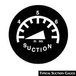
The air is drawn through a filter, to the instruments and then to the pump where it is vented to atmosphere. The pilot should consult the aircraft operating manual for specific information with regard to vacuum system normal operating values. Low gyro rotation speeds cause slow instrument response or lagging indications, while fast gyro speeds cause the instruments to overreact in addition to wearing the gyro bearings faster and decreasing gyro life.
2. ELECTRICAL POWER SYSTEM: An electric gyro, normally used to drive the turn coordinator or turn-and-slip indicator, operates like a small electric motor with the spinning gyro acting as the motor armature. Gyro speed in these instruments is approximately 8,000 rpm.
Aircraft that normally operate at high altitudes do not use a vacuum system to power flight instruments because pump efficiency is limited in the thin, cold air. Instead, alternating current (a.c.) drives the gyros in the heading and attitude indicators. The a.c. power is provided by inverters that convert direct current to alternating current. In some cases, the a.c. power is supplied directly from the engine-driven alternator or generator.
D. GYROSCOPIC INSTRUMENTS
1. ATTITUDE INDICATOR
BASIC COMPONENTS AND OPERATION
The purpose of the attitude indicator is to present the pilot with a continuous picture
of the aircraft's attitude in relation to the surface of the earth. The figure (below,
right) shows the face of a typical attitude indicator. It should be noted
that other attitude indicators differ in details of presentation.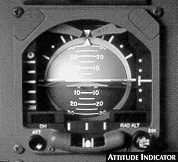
Pitch attitudes are depicted by the miniature aircraft's relative movement up or down in relation to the horizon bat, also called the gyro or attitude horizon. Usually at least four pitch reference lines arc incorporated into the instrument. Two are below the artificial horizon bar and two are above.
The bank indicator, normally located at the top of the instrument, shows the degree of bank during turns through the use of index marks. These are spaced at 10° intervals through 30°, with larger marks; placed at 30°, 60° and 90° bank positions.
The nose of the aircraft is depicted by a small white dot located between the fixed set of wings or by the point of the triangle as in the figure (See the bottom center of the Attitude Indicator figure, above right). The sky is represented by a light blue and the earth is shown by black or brown shading. Converging lines give the instrument a three-dimensional effect.
The small knob near the bottom of the instrument is used for vertical adjustment of the miniature aircraft. During straight-and-level flight the miniature aircraft should be adjusted so that it is superimposed on the horizon bat.
Once the artificial horizon line is aligned with the natural horizon of the earth during initial erection, the artificial horizon is kept horizontal by the gyro on which it is mounted. An erection mechanism automatically rights the gyro when precession occurs clue to maneuvers or friction. When the older-type gyro tumbles as a result of extreme attitude changes, the rotor normally precesses slowly back to the horizontal plane.
Even an attitude indicator in perfect condition can give slight erroneous readings. Small errors due to acceleration and deceleration are not significant because the erection device corrects them promptly; nonetheless, the pilot should be aware of them (refer to the paragraphs below). Large errors may be caused by wear, dirty gimbal rings, or out-of-balance parts. Warning flags (see Attitude Indicator figure, above right) may mean either that the instrument is not receiving adequate electrical power or that there is a problem with the gyro.
Principal Attitude Indicator Errors
TURN ERROR
During a normal coordinated turn, centrifugal force causes the gyro to precess toward the inside of the turn. This precession increases as the bank steepens; therefore, it is greatest during the actual turn. The error disappears as the aircraft rolls out at the end of a 180 degrees turn at a normal rollout rate.
Therefore, when performing a steep turn, the pilot may use the attitude indicator for rolling in and out of the turn, but should use other instruments (VSI and altimeter) during the turn for specific pitch information.
ACCELERATION ERROR
As the aircraft accelerates (e.g., during takeoff), there is another type of gyro precession which causes the horizon bar to move down, indicating a slight pitch up attitude. Therefore, takeoffs in low visibility require the use of other instruments such as the altimeter to confirm that a positive rate of climb is established immediately after takeoff.
DECELERATION ERROR
Deceleration causes the horizon bar to move up, indicating a false pitch down attitude.
ADDITIONAL ASPECTS
Because the attitude indicator is the most important instrument during IFR flight, the pilot should be aware of some additional uses and characteristics:
a) if the attitude indicator has not tumbled, it can assist the pilot greatly in recovering from unusual attitudes;
b) the attitude indicator displays the degree of bank used during a turn, bur it cannot provide information about the quality (coordination) of the turn. Coordination can be determined only by using the ball in the turn indicator; and
c) the rate of turn is not shown by the attitude indicator bur rather the turn indicator. When performing standard. rate turns, the pilot should establish the initial angle of bank by using the attitude indicator, then check the turn indicator to ascertain if the bank angle is correct. After making any necessary corrections, the pilot maintains the resulting bank on the attitude indicator.
2. HEADING INDICATOR: The heading indicator, shown in the figure below
(right), formerly called the directional gyro, uses the
principle of gyroscopic rigidity to provide a stable heading reference. The pilot should
remember that real precession, caused by maneuvers and internal instrument errors, as well
as apparent precession caused by aircraft movement and earth rotation, may cause the
heading indicator to "drift".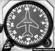
In newer heading indicators, the vertical card or dial on the instrument face appears to revolve as the aircraft turns. The heading is displayed at the top of the dial by the nose of the miniature aircraft (see the figure to the right). Another type of direction indicator shows the beading on a ring similar to the card. in a magnetic compass.
Because the heading indicator has no direction-seeking qualities of its own, it must be set to agree with the magnetic compass. This should be done only on the ground or in straight-and-level, unaccelerated flight when magnetic compass indications are steady and reliable.
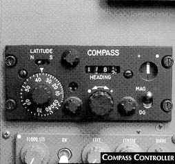 The pilot should set the heading indicator by turning the heading
indicator reset knob at the bottom of the instrument to set the compass card to the
correct magnetic heading. On large aircraft, this function is done using a compass
controller (See the Compass Controller figure, to the right).
The pilot should set the heading indicator by turning the heading
indicator reset knob at the bottom of the instrument to set the compass card to the
correct magnetic heading. On large aircraft, this function is done using a compass
controller (See the Compass Controller figure, to the right).
The pilot of a light aircraft should check the heading indicator against the magnetic compass at least every 15 minutes to assure accuracy. Because the magnetic compass is subject to certain errors , the pilot should ensure that these errors are not transferred to the heading indicator.
3. RATE AND QUALITY OF TURN INDICATORS: There are two types of rate and quality of turn indicators, the turn coordinator and the turn-and-slip indicator (See the Turn and Slip Indicator and Turn Co-ordinator figures, below, right).
Both of these gyroscopic instruments indicate the rate at which the aircraft is turning. The turn co-ordinator contains a miniature schematic aircraft to shown when the actual aircraft is turning. The turn-and-slip indicator, on the other band, has a vertical needle which deflects in the direction the aircraft is turning.
TURN-AND-SLIP INDICATOR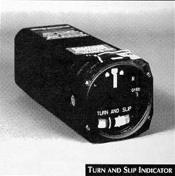
The turn-and-slip indicator (right) provides the only information of either wing's level or bank attitude if the other gyroscopic instruments should fail. This indicator is sometimes called the "needle and ball". This instrument, along with the airspeed indicator, magnetic compass and altimeter, can assist the pilot in flying through instrument weather conditions, even when it is the only gyro instrument operating.
The turn needle of the turn-and-bank indicator gives an indirect indication of the bank attitude of the aircraft. When the turn needle is exactly centered, the aircraft is in straight flight. When the needle is displaced from center, the aircraft is turning in the direction of the displacement. Thus, if the ball is centered, a left displacement of the turn needle means the left wing is low and the aircraft is in a left turn. Return to straight flight is accomplished by coordinating aileron and rudder pressures.
The ball of the turn-and-bank indicator is actually a separate instrument, conveniently located under the turn needle so the two instruments can be used together. This instrument is best used as an indication of attitude. When the ball is centered within its glass tube the maneuver is being executed in a coordinated manner. However, if the ball is out of its center location, the aircraft is either slipping or skidding . The side to which the ball has rolled indicates the direction of the slip or skid.
In a slip, the rate of turn is too slow for the angle of bank, and the lack of centrifugal force causes the ball to be displaced to the inside of the turn. (To correct, decrease the angle of bank, or use rudder to increase the rate of turn, or both). In a skid the rate of turn is too fast for the angle of bank, and excessive centrifugal force causes the ball to be displaced to the outside of the turn. (To correct, increase the bank angle, or use rudder to decrease the rate of turn, or both).
In coordinated flight, the needle may be used to measure the rate of turn; in a "standard rate turn", the needle is aligned with the left or right marker (dog-house) and the aircraft will turn at the rate of 3° per second or 180° in one minute. Hence, in these conditions, the needle indicates both direction and rate of turn.
The answer to controlling and trimming an aircraft in straight and level flight by means of the turn-and-bank indicator requires a return to basic control principles - i.e., control yaw with the rudder and keep the wings level with aileron. Therefore, when flying straight and level through the use of the turn-and-bank indicator, prevent yawing with appropriate rudder pressure, and keep the wings level with appropriate aileron pressure. The needle will not deflect while heading is constantly maintained, since no turn exists.
In other words, control the ball with rudder since the ball moves parallel to a plane passing through the rudder pedals, and control the needle with aileron since the ailerons affect bank angle, a primary requirement for a normal turn.
It is important that both the needle and ball are used together. The problem associated with using these instruments separately is that although the ball will positively indicate that the aircraft is slipping or skidding, just which one of these the aircraft is doing can only be determined by reference to the needle. Furthermore, the needle will not positively indicate a bank attitude. An aircraft could be in a bank attitude and yet the needle could remain centered or indicate a turn in the opposite direction, if controls are not coordinated.
TURN CO-ORDINATOR
Most current aircraft have a turn coordinator that replaces the older
turn-and-slip instrument. A small aircraft silhouette rotates to show how the aircraft is
turning (see the figure below, right). When the aircraft turns left or right, the aircraft
silhouette banks in the direction of the turn. When the wing of the aircraft silhouette is
aligned with one of the lower index marks, the aircraft is in a standard-rate turn
30°/sec.).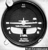
This instrument also senses the roll rate because the gyro is tilted on its fore and aft axis. The electric gyro is canted approximately 35°; therefore, the miniature aircraft banks whenever the actual aircraft rotates about either the yaw or roll axis. This freedom of movement enables the gyro to indicate immediately when the aircraft is turning. After the bank angle for a turn is established and the roll rate is zero, the aircraft symbol indicates only the rate of turn.
The miniature aircraft moves independently of the ball or inclinometer. The position of the ball indicates the quality of the turn. When the miniature aircraft depicts a turn and the ball is not centered, it shows that the turn is not coordinated (see black ball in figure on the right).
If the miniature aircraft is level and the ball is displaced to either side (see ball in above figure on the right), the aircraft is flying straight but with one wing low.
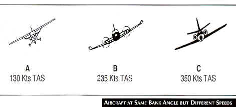 The pilot should understand the relationship of
true airspeed and angle of bank as it affects the rate and radius of turn. The
Aircraft at Same Bank Angle But Different Speeds figure (right) shows three
aircraft flying with the same angle of bank but at different airspeeds. The aircraft with
the greatest rate of turn is aircraft A. If two aircraft arc turning at the same angle of
bank, the slower aircraft has the shorter turning radius and also a greater rate of turn.
The pilot should understand the relationship of
true airspeed and angle of bank as it affects the rate and radius of turn. The
Aircraft at Same Bank Angle But Different Speeds figure (right) shows three
aircraft flying with the same angle of bank but at different airspeeds. The aircraft with
the greatest rate of turn is aircraft A. If two aircraft arc turning at the same angle of
bank, the slower aircraft has the shorter turning radius and also a greater rate of turn.
A common misconception is that faster aircraft will complete a 360° turn in the least time. For example, a jet in a 20° bank flying at a true airspeed of 350 kts requires approximately 5.3 minutes to complete a 360° turn. Aircraft A, with also a 20° bank but a true airspeed of 130 knots (kts), requires just two minutes to complete a 360° turn.
The radius of turn also increases with an increase in airspeed, varying with the square of the true airspeed. Therefore, because the speed of aircraft C is about three times that of aircraft A, the turning radius of aircraft C is approximately nine times that of aircraft A.
4. THE GYROSYN COMPASS SYSTEM: A gyrosyn compass system has a remotely located unit for sensing the earth's magnetic field. It incorporates a gyroscope to provide stability. Electrical power is required for its operation.
A variety of cockpit indicators may be driven by a gyrosyn compass system, including fixed-card instruments, or moving-card indicators such as a radiomagnetic indicator (RMI) or a horizontal situation indicator (HSI).
All gyrosyn compass systems have a set of basic components whose operation is similar, regardless of the aircraft type:
a) REMOTE COMPASS TRANSMITTER: The remote compass transmitter senses the earth's magnetic field. It is usually remotely located to reduce aircraft magnetic disturbances. The sensing element is pendulously suspended within a sealed bowl (fluid-filled to prevent excessive swinging) and maintains a horizontal plane within a pitch attitude of +30 degrees. During large changes in heading, airspeed or pitch the sensing clement is displaced from the horizontal plan and produces erroneous signals. These generally have little effect because of the stability
provided by the gyro, and a return to straight-and-level, unaccelerated flight again provides correct orientation signals;
b) GYROSCOPE: The gyroscope principle of rigidity in space is applied to retain a fixed position during any aircraft turns. Turning motion of the aircraft about the gyro is then electrically relayed to the beading indicator;
c) ERECTION MECHANISM: An erection torque motor is used to keep the gyro spin axis in a horizontal plane;
d) AMPLIFIER: The amplifier is the coordination and distribution center for all system electrical signals. Remote compass transmitter signals arc phase detected to resolve for the 180-degree ambiguity and arc sent to the slaving torque motor to keep the gyro spins axis aligned with magnetic north-south. The amplifier also provides high voltage to the slaving torque motor for any periods of fast slaving; and
e) HEADING INDICATOR UNIT
NOTE: Some gyrosyn compass systems are capable of non-slaved operation in extreme northern or southern latitudes where the earth’s magnetic field is distorted or weak. In this situation:
Send all comments to ![]() aeromaster@eng.fiu.edu
aeromaster@eng.fiu.edu
© 1995-98 ALLSTAR Network. All rights reserved worldwide.
| Funded in part by |
Updated: February 23, 1999