 |
|||||
| Home | Research | For Teachers | HISTORY Level 1 Level 2 Level 3 |
PRINCIPLES Level 1 Level 2 Level 3 |
CAREER Level 1 Level 2 Level 3 |
| Gallery | Hot Links | What's New! | |||
| Web Administration and Tools | |||||
|
|||||
| Home | Research | For Teachers | HISTORY Level 1 Level 2 Level 3 |
PRINCIPLES Level 1 Level 2 Level 3 |
CAREER Level 1 Level 2 Level 3 |
| Gallery | Hot Links | What's New! | |||
| Web Administration and Tools | |||||
Flight Instruments - Level 3
![]()
A. GENERAL
A flight director system (FDS) combines many of the previously described instruments to provide an easily interpreted display of the aircraft's flight path. The pre-programmed path, automatically computed, furnishes the steering commands necessary to obtain and hold a desired path.
The major components of a flight director system are the flight director indicator (FDI), a horizontal situation indicator (HSI), a mode selector and a flight director computer. The following paragraphs describe a common type of FDS.
B. FLIGHT DIRECTOR INDICATOR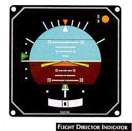
Elements of a flight director indicator (see figure, right) are:
1. FIXED AIRCRAFT SYMBOL: The aircraft's attitude relative to the natural horizon is shown by the aircraft symbol and flight command bars. The pilot can adjust the symbol to one of three flight modes. To fly the aircraft with the command bars armed, the pilot simply inserts the aircraft symbol between the command bars.
2. COMMAND BARS: The command bars move up for a climb or down for descent, and roll left or right to provide lateral guidance. They display the computed angle of bank for standard-rate turns to enable the pilot to reach and fly a selected beading or track. The bars also show pitch commands that allow the pilot to capture and fly an ILS glide slope, a preselected pitch attitude, or maintain a selected barometric altitude. To comply with the directions indicated by the command bars, the pilot maneuvers the aircraft to align the fixed symbol with the command bars. When not using the bars, the pilot can move them out of view.
3. GLIDE SLOPE INDICATOR: The glide slope deviation pointer represents the center of the instrument landing system (ILS) glide slope and displays vertical deviation of the aircraft from the glide slope center. The glide slope scale centerline shows aircraft position in relation to the glide slope.
4. LOCALIZER DEVIATION POINTER: The deviation pointer, a symbolic runway, represents the center of the ILS localizer, and comes into view when the pilot has acquired the glide slope. The expanded scale movement shows lateral deviation from the localizer and is approximately twice as sensitive as the lateral deviation bar in the horizontal situation indicator.
SLIP INDICATOR: This provides prompt slip or skid indications.
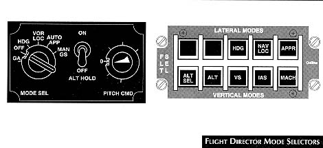 FLIGHT DIRECTOR CONTROL PANEL: The mode selector switch and control
panel (see Flight Director Mode Selectors figure, right) provides the
input information used by the FDS to compute the command and display required for the FDI.
FLIGHT DIRECTOR CONTROL PANEL: The mode selector switch and control
panel (see Flight Director Mode Selectors figure, right) provides the
input information used by the FDS to compute the command and display required for the FDI.
The pitch command control pre-sets the desired pitch angle of the aircraft for climb or descent. The command bars on the FDS then display the computed attitude to maintain the pre-selected pitch angle. The pilot may choose from among many modes including the HDG (heading) mode, the VOR/LOC (localizer tracking) mode, or the AUTO APP or G/S (automatic capture and tracking of ILS localizers and glide path) mode. The auto mode has a fully automatic pitch selection computer that takes into account aircraft performance and wind conditions, and operates once the pilot has reached the ILS glide slope. More sophisticated systems allow more flight director modes.
Turning the control clockwise commands a climb, and counter-clockwise, a descent. The GS (manual glide slope) mode allows the pilot to manually reach and maintain the glide slope through pitch command indications. The GA (go around) mode provides climb command information. The pilot places the command bars in a climb pitch, which is pre-set based on the aircraft performance and remains constant. The pilot may use the GA mode in conjunction with automatic throttle/speed control.
NOTE: The manual glide slope selection normally is used when the pilot intercepts the slope from above.
The ALT HOLD (altitude hold) switch may be operated in the HDG and VOR/LOC modes. Before the aircraft reaches the glide path, the pilot can also operate the switch in the AUTO APP mode. When engaged, pitch commands are referenced to the current barometric altitude indicated on the altimeter. The command bars on the FDI provide the climb or descent information required to maintain the altitude.
C. HORIZONTAL SITUATION INDICATOR
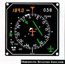 The horizontal situation indicator (HSI) was
developed to assist pilots to interpret and use aircraft navigational aids. There are
various types of HSIs, but each performs the same function. The HSI (see figure, right)
displays information obtained from combinations of the heading indicator, radio magnetic
indicator (RMI), track indicator and range indicator. It may also display VOR, DME, ILS or
ADF information.
The horizontal situation indicator (HSI) was
developed to assist pilots to interpret and use aircraft navigational aids. There are
various types of HSIs, but each performs the same function. The HSI (see figure, right)
displays information obtained from combinations of the heading indicator, radio magnetic
indicator (RMI), track indicator and range indicator. It may also display VOR, DME, ILS or
ADF information.
The aircraft heading is displayed on a rotating compass card under the heading lubber line. The card is calibrated in 5° increments. The hearing pointer provides magnetic bearing information from the aircraft to the selected ground station (VOR or ADF). The fixed aircraft symbol and floating track bar display the aircraft's position relative to the selected track (VOR or ILS localizer).
When a VOR station is selected, the inner dot on the track bar azimuth scale indicates approximately 5° and the outer dot approximately 10° (the aircraft's operating manual should give details). In ILS applications the inner dot indicates approximately 1 1/4° and the outer dot approximately 2 ˝°, depending on the actual width of the localizer. The distance measuring equipment (DME) displays slant ranges in nautical miles to the selected DME station and, depending on the installation, may operate in the ILS Mode.
The pilot may adjust the track selector to indicate any of 360° tracks. To select a desired track, the pilot rotates the head of the track arrow by turning the track selector knob to the desired track on the compass card, and then checks the track selector window for precise setting. When the TO-FROM indicator points to the head of the track arrow, it indicates that the selected track, if intercepted and flown, will lead the aircraft to the station. This may be reversed by selecting the reciprocal track on the compass card.
To intercept the inbound track, the pilot sets the desired track in the selector window and crosschecks the TO-FROM indicator to make sure that it points to the head of the track arrow. The pilot turns the aircraft in the shortest direction to an interception heading (normally 30°-45°). The pilot then flies the intercept angle, ensuring that the head of the track arrow is in the top half of the HSI with an adequate interception angle. The bearing pointer should be between the heading lubber line and the head of the track arrow. The angle should not exceed 90° from the selected track.
For outbound tracking, the pilot selects the desired track in the selector window and ensures that the TO-FROM indicator points toward the tail of the track arrow. The pilot then turns the aircraft in the shortest direction to an interception track that places the head of the track arrow in the upper half of the HSI with a suitable interception angle (normally 45°).
Immediately after passing the station, the pilot intercepts the outbound track by turning the aircraft to parallel the track. The pilot sets the outbound track in the selector window. When the track bar and bearing pointer stabilize, the pilot notes the degrees off track and turns towards the track by this amount, allowing for wind drift. The intercept angle should not exceed 45°.
D. FLIGHT DIRECTOR COMPUTER
The basic flight director computer receives information from the:
The computer uses this data to provide steering command information that enables the pilot to:
E. OTHER TYPES OF FLIGHT DIRECTOR SYSTEMS
Flight director systems vary greatly. In aircraft equipped with Flight Management Systems (FMS), the flight director is much more sophisticated and receives input from various sensors and one or more air data computers. Therefore, the pilot must consult the operating instructions for the particular aircraft model for specific information,
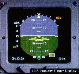
F. ELECTRONIC FLIGHT INSTRUMENT SYSTEM (EFIS)
EFIS refers to a system where conventional electro-mechanical flight instruments have been replaced by cathode ray tubes (CRT). These CRTs electronically display flight information in much the same presentation as electro-mechanical instruments bur they also have the flexibility for selecting additional information to be added to the display and for altering the presentation.
The two most commonly used EFIS instruments are the electronic horizontal situation indicator (EHSI) and the electronic attitude director indicator (EADI) (see EFIS Primary Flight Display figure, below right, and EFIS Navigation Display figure, below the Flight Display figure). These can also be called an ND (Navigation Display) or a PFD (Primary Flight Display). The system may also include a multifunctional display (MFD) on a larger CRT which can provide expanded displays of HSI, radar, and navigation data from flight instruments and can include other data such as checklists, emergency procedures, etc. Data from various sources can be integrated into various combinations of displays depending on the equipment installed.
 The EFIS uses input data from several sources including:
A typical EFIS is composed of a Primary Flight Display. a Navigation Display, a Display
Select Panel, a Display Processor Unit, a Weather Radar Panel, a Multifunction Display,
and a Multifunction Processor Unit.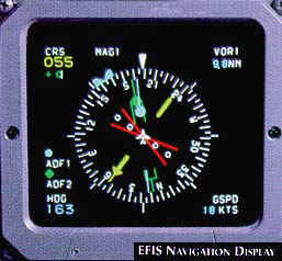
1. PRIMARY FLIGHT DISPLAY (PFD): The typical PFD is a multicolor CRT or LCD display unit that presents a display of aircraft attitude and flight control system steering commands including VOR, localizer, TACAN, or RNAV deviation; and glideslope or preselected altitude deviation. Flight control system mode annunciation, auto-pilot engage annunciation, attitude source annunciation, marker beacon annunciation, radar altitude, decision height set and annunciation, fast-slow deviation or angle-altitude alert, and excessive ILS deviation (when Category II configured) can also be displayed (see EFIS Primary Flight Display figure, above right).
2. NAVIGATION DISPLAY (ND): The typical ND is a multicolor CRT or LCD display unit that presents a plan view of the aircraft horizontal navigation situation. Information displayed includes compass beading, selected heading, selected VOR, localizer, or RNAV course and deviation (including annunciation or deviation type), navigation source annunciation, digital selected course/desired track readout, excessive ILS deviation (when Category II configured), to/from information, back course localizer annunciation, distance to station/waypoint, glideslope MGP, or VNAV deviation ground speed, time-to-go, elapsed time or wind, course information and source annunciation from a second navigation source, weather radar target alert, waypoint alert when RNAV is the navigation source, and a bearing pointer that can be driven by VOR, RNAV or ADF sources as selected on the display select panel. The ND can also be operated in an approach format or an en route format with or without weather radar information included in the display (see EFIS Navigation Display figure, above right).
3. DISPLAY SELECT PANEL (DSP): The display select panel provides navigation sensor selection, bearing pointer selection, format selection, navigation data selection (ground speed, time-to-go, time, and wind direction/speed), and the selection of VNAV (if the airplane has a VNAV system), weather, or second navigation source on the ND. A DH SET knob that allows decision height to be set on the PFD is also provided. Additionally, course, course direct to, heading, and heading sync are selected from the DSP.
4. DISPLAY PROCESSOR UNIT (DPU): The display processor unit provides sensor input processing and switching, the necessary deflection and video signals, and power for the electronic flight displays. The DPU is capable of driving two electronic flight displays with different deflection and video, signals. For example, a PFD on one display and an ND on the other.
5. WEATHER RADAR PANEL (WXP): The weather radar panel provides MODE control (OFF, STBY, TEST, NORM, WX, and MAP), RANGE selection (10, 25, 50, 100, 200 and 300 nm), and system operating controls for the display of weather radar information on the MFD and the ND's when RDR is selected on the MFD and/or the display select panel.
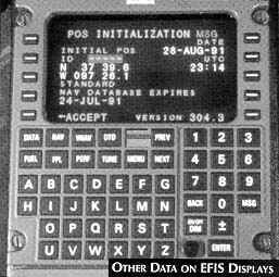 6. MULTIFUNCTION DISPLAY (MFD): The multifunction display is a
multicolor CRT or LCD display unit that mounts in the instrument panel in the space
normally provided for the weather radar indicator. Standard functions displayed by the
unit include weather radar, pictorial navigation map, and in some systems, check list and
other operating data. Additionally, the MFD can display flight data or navigation data in
case of the malfunction in either of the PFD's or ND's (see Other Data on EFIS
Display figure, right).
6. MULTIFUNCTION DISPLAY (MFD): The multifunction display is a
multicolor CRT or LCD display unit that mounts in the instrument panel in the space
normally provided for the weather radar indicator. Standard functions displayed by the
unit include weather radar, pictorial navigation map, and in some systems, check list and
other operating data. Additionally, the MFD can display flight data or navigation data in
case of the malfunction in either of the PFD's or ND's (see Other Data on EFIS
Display figure, right).
7. MULTIFUNCTION PROCESSOR UNIT (MPU):
The multifunction processor unit provides sensor input processing and switching and the necessary deflection and video signals for the multifunction display. The MPU can provide the deflection and video signals to the PFD and ND displays in the event of failures to either or both display processor units.
EFIS furnishes the pilot with the following common features:
Note: This chapter has dealt very generally with a generic EFIS. It is important that specific aircraft operating procedures be consulted for detailed information.
Send all comments to ![]() aeromaster@eng.fiu.edu
aeromaster@eng.fiu.edu
© 1995-98 ALLSTAR Network. All rights reserved worldwide.
| Funded in part by |
Updated: February 23, 1999