 |
|||||
| Home | Research | For Teachers | HISTORY Level 1 Level 2 Level 3 |
PRINCIPLES Level 1 Level 2 Level 3 |
CAREER Level 1 Level 2 Level 3 |
| Gallery | Hot Links | What's New! | |||
| Web Administration and Tools | |||||
|
|||||
| Home | Research | For Teachers | HISTORY Level 1 Level 2 Level 3 |
PRINCIPLES Level 1 Level 2 Level 3 |
CAREER Level 1 Level 2 Level 3 |
| Gallery | Hot Links | What's New! | |||
| Web Administration and Tools | |||||
Navigation Systems - Level 3
![]()
A. GENERAL
Distance measuring equipment (DME), used by many pilots because of its convenience during flight, consists of airborne and ground equipment usually co-located. The DME provides distance (and in some systems groundspeed) information only from the ground facility. DME(P) is precision DME used in conjunction with MLS.
DME operates in the UHF frequency band however its frequency can be "paired" with VOR or ILS or localizer (LOC) frequencies. The receiving equipment in most aircraft provide for automatic DME selection through a coupled VOR/lLS receiver. Selection of the appropriate VOR or ILS frequency automatically tunes the DME.
DME information can also be received from a TACAN station by tuning in the "paired" frequency. This VHF frequency will be found in the navigation data box for the ground facility listed on the en route IFR chart.
The DME operates in the ultra-high frequency (UHF) band and therefore is restricted to line-of-sight transmission. With adequate altitude, the pilot can receive en route DME signals at distances over 200 NM, with an error of ±0.25 nautical miles (NM) or 1.25% of the distance, whichever is greater. Approach DMEs paired with an ILS or LOC have a nominal range of about 40 NM.
B. BASIC PRINCIPLES
The DME operates by transmitting to and receiving paired pulses from the ground station. The transmitter in the aircraft sends out very narrow pulses at a frequency of about 1,000 MHz. These signals arc received at the ground station and trigger a second transmission on a different frequency. These reply pulses arc sensed by timing circuits in the aircraft's receiver that measure the elapsed time between transmission and reception. Electronic circuits within the radio convert this measurement to electrical signals that operate the distance and ground speed indicators.
C. DME COMPONENTS AND OPERATIONS
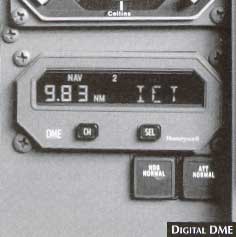 The transceiver (see Digital DME figure, on the
right) that sends out the interrogating signal to the ground station contains an internal
computer to measure the time interval that elapses until the response. The antenna, used
for both transmission and reception, is a very small "sharks fin" normally
mounted on the underside of the aircraft. Modern DME controls incorporate digital readouts
of frequency, DME and groundspeed information.
The transceiver (see Digital DME figure, on the
right) that sends out the interrogating signal to the ground station contains an internal
computer to measure the time interval that elapses until the response. The antenna, used
for both transmission and reception, is a very small "sharks fin" normally
mounted on the underside of the aircraft. Modern DME controls incorporate digital readouts
of frequency, DME and groundspeed information.
The DME displays information in the form of distance to the station and the aircraft's groundspeed. Most DME radios exhibit this data on the face of the radio. The distance to the station is a slant range, expressed in nautical miles. For example, if an aircraft were directly over the DME station at 6,100 ft AGL, the distance indicator would read one mile (see Slant Range Measurements figure, below right).
The DME receiver can express groundspeed in knots. This value is accurate only
if the aircraft is flying directly to or from the station, because the DME measures
groundspeed by comparing the time lapse between a series of pulses. When accurate, the
groundspeed information allows the pilot to make accurate estimates of time of arrival and
accurate checks of aircraft progress.
When the pilot turns the function control knob of the DME receiver to "groundspeed", there is not an immediate readout because the DME must be on the groundspeed function long enough to compare the time lapse between several pulse signals.
Certain DME radios have a frequency-hold function. These radios are channeled by the primary VHF navigation radio. When the pilot selects the VOR frequency, the DME also channels. The DME hold function retains the frequency of the original VORTAC station on the DME while the pilot channels the VOR receiver to another frequency.
A pilot with DME may pinpoint aircraft position using the radial of a VORTAC and the distance information from the same VORTAC; whereas a pilot without DME must use radials from two stations to get a position fix. The pilot also can use DME to establish intersections and holding patterns. When so equipped and cleared by ATC, pilots can establish holding patterns by reference to radials and DME.
Many airports have instrument approach procedures based on use of VOR and DME equipment. Normally, an aircraft making this type of approach has lower minimums than when only the VOR is used.
D. FLYING A DME ARC
 1. CALM CONDITIONS: Theoretically, with no wind, a 20° turn every
20° of arc will keep the aircraft close to the desired arc (see Segments of a DME
Arc figure, on the right). Although a DME arc may be flown using a standard VOR
navigation indicator for bearing information, pilot orientation and turning points are
simplified by using an RMI.
1. CALM CONDITIONS: Theoretically, with no wind, a 20° turn every
20° of arc will keep the aircraft close to the desired arc (see Segments of a DME
Arc figure, on the right). Although a DME arc may be flown using a standard VOR
navigation indicator for bearing information, pilot orientation and turning points are
simplified by using an RMI.
The pilot can fly the arc most easily by allowing the tail of the RMI needle to move 10° ahead of the wingtip position. The subsequent 20° turn places the tail of the needle 10° behind the wingtip position. The pilot holds this beading until the tail of the needle moves to 10° ahead of the wingtip, and so on. (Arcs are never less than 7 NM DME or more than 30 NM DME). Depending on the distance to the VOR/DME, the aircraft will drift inside of and then beyond the desired arc. The pilot should attempt to keep the aircraft within plus or minus 0.5 NM of the arc. The obstacle clearance area associated with a DME arc is ±4 NM.
The figure Staying on a DME Arc, below right, shows one way of staying
on the arc.
STEP l
STEP 2
STEP 3
2. WIND DRIFT: When flying in a wind pilots require practice before they can modify the procedure above to keep the aircraft close to the arc. Unlike drift correction on a straight track, the drift changes as the aircraft proceeds around the arc. The pilot should estimate the new beading, make a positive turn and bold the beading until the DME and RMI readouts show that it is time to turn again.
3. ARCING TO A FINAL APPROACH:
Example:
20 NM DME Arc (see Final Approach Arc figure, below
right) 
Send all comments to ![]() aeromaster@eng.fiu.edu
aeromaster@eng.fiu.edu
© 1995-98 ALLSTAR Network. All rights reserved worldwide.
| Funded in part by |
Updated: February 23, 1999