CHAPTER V
RESIDENTIAL WIRING
5.1. THE SERVICE ENTRANCE
Buildings and other structures receive the electrical energy through the service entrance. In residential wiring, the electric company supply this energy through three conductors: two phase conductors (hot), and one ground (neutral). Between any phase conductor and ground there is a voltage of 120 V., and between the two phase conductors, 240 V. The service conductors come from the electric company transformer under the ground level (underground service) or at certain specified height (overhead service), as shown in Figure 5.1. On the same figure may be seen the different elements participating in the service entrance.

On Figure 5.2 A) and B), may be seen a front view of a service entrance. Only power service-drop conductors are permitted to be attached and supported by the service mast. The code does not permit to attach or support television or telephone cables.


Figure 5.2. Front view of a service entrance.
Overhead service is comprised of conductors that are spanned overhead from the electric company’s pole to a point of attachment to the building. At this place they are connected to the service entrance conductors which have been installed in the service entrance raceway. The article 230 of the NEC® define the minimum sizes and clearances that shall be maintained by the service entrance conductors. It is established that the conductors shall have sufficient ampacity to carry the current for the loads they serve and shall have adequate mechanical strength. The conductors will be minimum No. 8 copper or No. 6 aluminum or copper-clad aluminum. The vertical clearances from ground for service-drop conductors up to 600 V are given in article 230-24 (B) of the NEC® and are shown in Figure 5.3.
A) Building electric entrance or sidewalks.
B) Over Residential properties and driveways or commercial areas not subject to truck traffic.
C) The same as B) but when the voltage exceeds 300 V to ground.
D) Over public streets, alleys, roads, etc.
Figure 5.3. Clearances
5.2. –THE GROUNDING SYSTEM
The grounding connection at the service entrance can be seen on Figure 5.1. All the equipment grounding in the house is connected to this grounding system at the main entrance. Article 250 of the NEC® deals with the different possibilities of connecting to ground. The grounding electrode system in a building will include at least one of the following:
· A ¾” metal underground water pipe in direct contact with the earth for 10 ft or more, and located at no more than 5 feet from the point of entrance to the building.
· The metal frame of the building or structure, where effectively grounded,
· An electrode encased by at least 2” of concrete, located within and near the bottom of a concrete foundation or footing that is in direct contact with the earth, consisting of at least 20 ft of rods of no less than ½” diameter, or bare copper conductor not smaller than No. 4.
· A ground ring of bare copper No. 2 conductor encircling the building or structure, in direct contact with the earth at a depth not smaller than 2 ½ ft, and a length of at least 20 ft.
· Rod electrodes of iron or steel at least 5/8” in diameter, buried to a depth of not less than 8 ft under the grade level and not less than 6 ft apart from each other, as shown in Figure 5.4.
Figure 5.4. Rod electrodes installation.
· Plate electrodes. Each plate electrode shall expose no less than 2 sq. ft. of surface to exterior soil.
Also other local metal underground systems or structures such as piping systems and
underground tanks are permitted.
The grounding conductor is connected to the grounding electrode by exothermic welding, listed lugs, listed pressure connectors, listed clamps, or other listed means. Figure 4.5 shows two possible ways of connection.
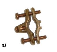
Figure 5.5. Conductor connection to the electrode. A) ground clamp; B) U-bolt ground clamp.
The minimum size of the grounding electrode conductor can not be less than the given in Table 250-66 from the NEC®. These values are partially reproduced in Figure 5.6.
| Size of Largest Service-Entrance Conductor or Equivalent Area for Parallel Conductors | Size of Grounding Electrode Conductor |
| 2 or smaller | 8 |
| 1 or 1/0 | 6 |
| 2/0 or 3/0 | 4 |
| Over 3/0 through 350 kcmil | 2 |
| Over 350 kcmil through 600 kcmil | 1/0 |
| Over 600 kcmil through 1100 kcmil | 2/0 |
| Over 1100 kcmil | 3/0 |
Figure 5.6. Grounding Electrode Conductor for Alternating-Current Systems ( for copper only)
Reprinted with permission from NFPA 70-1999, the National Electrical Code®, Copyright© 1998, National Fire Protection Association, Quincy, MA 02269. This reprinted material is not the referenced subject which is represented only by the standard in its entirety.
5.3. –OVERCURRENT DEVICES
Overcurrent protection is one of the most important components of any electrical system. The function of an overcurrent device is to open the circuit when an overload or short circuit occurs. The requirements for overcurrent protection are contained in the Article 240 of the NEC®.
Two types of overcurrent devices are currently used: circuit breakers and fuses. The standard ampere ratings for nonadjustable circuit breakers and fuses are contained in Section 240-6 of the NEC®, and are the following: 15, 20, 25, 30, 35, 40, 45, 50, 60, 70, 80, 90, 100, 110, 125, 150, 175, 200, 225, 250, 300, 350, 400, 450, 500, 600, 700, 800, 1000, 1200, 1600, 2000, 2500, 3000, 4000, 5000, and 6000.
The basic purpose of overcurrent protection is to open the circuit before conductors or it's insulation is damaged when an overcurrent occurs. The fuses and breakers shall have an interrupting rating sufficient for the nominal circuit voltage and the current that is available at the line terminals of the equipment (NEC®, Section 110-9). The total load on any overcurrent device located in a panelboard shall not exceed 80 percent of its rating where, in normal operation, the load will continue for three hours or more [NEC®, Section 384-16 (d)]. Figure 5.7 shows in A) a single breaker, used in residential wiring for 120 volts loads, and in B) a double pole breaker for interrupting 240 volt circuits appliances.
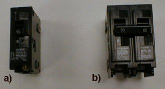
Figure 5.7. Overcurrent Devices. A) Single-pole breaker. B) double-pole breaker.
5.4. –PANELBOARDS AND SWITCHBOARDS
The panelboard is connected after the service disconnecting means, frequently inside the building. The NEC® defines a panelboard as a single panel or group of panel units designed for assembly in the form of a single panel; including buses, automatic overcurrent devices and equipped with or without switches for the control of lights, heat or power circuits; designed to be placed in a cabinet or cutout box placed in or against a wall or partition and accessible only from the front.
In Figure 5.8 a panelboard and its related wiring is shown. In residential wiring, only three conductors enter the residence the two phase conductors and the neutral, which is connected to the neutral and ground bus bars if the panelboard is installed at the main entrance. In the case of subpanels, neutral and ground bars are separated. Article 384 of the NEC® presents panelboards and switchboards.

Figure 5.8. Wiring a Panelboard
The maximum number of overcurrent devices in a panelboard is 42. Its number is determined by the needs of the facility being served. Panelboards are available in various sizes including 100, 225, 400, and 600 Amperes. Figure 5.9 presents a schematic of the way the buses and overcurrent devices are connected in a residential panelboard.

Figure 5.9. Single phase lighting and appliance branch-circuit panel board
The service disconnecting device shown in Figure 5.1 is a fused switch used for manually interrupt the entrance circuit. The fuses shall be rated at the same value selected for the main breaker in the panelboard. Fused switches are available in ratings of 30, 60, 100, 200, 400, 600, 800, 1200, 1600, 2000, 2500, 3000, 5000, and 6000 amperes in both 250 and 600 volts. The ampere rating for the switch will be equal or higher than the ampere rating of the contained fuses.
5.5. –BRANCH CIRCUITS
The NEC® defines the branch circuits as the circuit conductors between the final over-current device protecting the circuit and the outlet(s). The difference between the branch circuits and the feeders is that these last conductors run between the service equipment and the panel-boards.
A general purpose branch circuit supplies a number of outlets for lighting and appliances, while an individual branch circuit supplies only one utilization equipment. Where the branch circuit supplies continuous and/or non-continuous loads , the minimum branch circuit conductor size, before the application of any adjustment or correction factors, shall have an allowable ampacity equal or greater than the non-continuous load plus 125 percent of the continuous load [NEC® 210.20(A)]. The continuous load is defined as a load where the maximum current is expected to continue for three hours or more.
Example 5.1: Calculate the wire size for a branch circuit feeding a 5 kW water heater in a dwelling.
The water heater is connected to 240 volts. The current is given by:
I = P/V = 5000/240 = 20.8 A
According to Table 310-16, No. 10 AWG copper conductors comply with the requirement.
Example 5.2: Calculate the wire size for a branch circuit feeding a 1.2 kW garbage disposal.
The garbage disposal is connected to 120 volts. The current is given by:
I = P/V = 1200/120 = 10 A
According to Table 310-16, No. 14 AWG copper conductors comply with the requirement.
Example 5.3: Calculate the minimum number of lighting circuits for a 2400 sq. ft. dwelling.
· From Table 220-3(a) of the NEC®, the general lighting load for residences is calculated assuming 3 VA/ft2. For this particular case: VA = 3 x 2400 = 7200.
· The total load in amperes will be: 7200/120 = 60
· The minimum number of 20 A circuits is: 60/20 = 3, or
· The minimum number of 15 A circuits is: 60/15 = 4
Regional codes are in some cases more rigid than the NEC®. As an example may be cited that the South Florida Building Code establish the maximum number of outlets per circuit for residential occupancies using the 12 points rule that assign one point for each light and two for each receptacle. The combination of lights and receptacle connected to a circuit can not give more than 12 points. Applying this rule, the actual number of general lighting circuits is always much bigger than the previously obtained number.
5.6. –RESIDENTIAL FEEDER CALCULATION
In order to calculate the necessary feeder at the service entrance it is mandatory to know the value of the different loads connected to the system. When preparing the wiring plans of a dwelling there are several conditions to comply with. Some of the more important are enumerated in the following paragraphs:
1) Single-phase
Dwelling Services and Feeders
· The size of the service entrance conduits is determined from the Table
C-8(A) [NEC®], which is partially reproduced in Figure 5.10.
| Type | Conductor Size(AWG) | Trade Size (in) | ||||||
| ½ | ¾ | 1 | 11/4 | 11/2 | 2 | 2 ½ | ||
| THWN-2 | 4 | 1 | 3 | 5 | 8 | 11 | 18 | 26 |
| 2 | 1 | 1 | 3 | 6 | 8 | 13 | 19 | |
| 1 | 1 | 1 | 2 | 4 | 6 | 10 | 14 | |
| 1/0 | 1 | 1 | 1 | 4 | 5 | 8 | 12 | |
| 2/0 | 1 | 1 | 1 | 3 | 4 | 7 | 10 | |
| 3/0 | 0 | 1 | 1 | 2 | 3 | 6 | 8 | |
| 4/0 | 0 | 1 | 1 | 1 | 3 | 5 | 7 | |
Figure 5.10. Maximum number of Compact Conductors in Rigid Metallic Conduit
Reprinted with permission from NFPA 70-1999, the National Electrical Code®, Copyright© 1998, National Fire Protection Association, Quincy, MA 02269. This reprinted material is not the referenced subject which is represented only by the standard in its entirety.
· If a single 3-wire, single-phase, with service entrance conductors in raceway or cable that supply a dwelling unit, the reduced conductor size from Section 310.15(B )(6) is applicable to the service entrance conductors. A partial reproduction of this Table for copper conductors only is shown in Figure 5.11.
|
Conductor (AWG or kcmil) Service or Feeder Rating (Amperes)
4 100 3 110 2 125 1 150 1/0 175 2/0 200 3/0 225 4/0 250 250 300 350 350 400 400 |
Figure 5.11. Conductor sizes
Reprinted with permission from NFPA 70-1999, the National Electrical Code®, Copyright© 1998, National Fire Protection Association, Quincy, MA 02269. This reprinted material is not the referenced subject which is represented only by the standard in its entirety.
2)
Clothes Dryer
· The load for household electric clothes dryers in a dwelling can not be less than 5 kW [Article 220.18].
· At least one additional 20 Amp (1500VA) branch circuit shall be provided to supply the laundry receptacle outlet(s) [ Article 210.11(C)(2)]
· At least one additional 20 Amp (1500VA) branch circuit shall be provided to supply the bath room receptacle outlet(s). Such circuits shall have on other outlets. [Article 210. 11(C)(3)].
· In the kitchen and associated rooms, at least two additional 20-Amp (1500 VA) small-appliance circuits shall be installed. The refrigerator may be connected to one of these circuits. Such circuits are not permitted to serve any other outlet , as exhaust hoods, disposals or dishwashers [Article 210-52 (B)].
Exception No. 1 permits the inclusion of switched receptacles supplied from a general-purpose branch circuit, in addition to the previously specified circuits.
· The receptacle outlet for refrigeration equipment shall be permitted to be supplied also from an individual branch circuit rated 15 Amp or greater [Article 210-52 (B), exception 2].
4) Arc-Fault Circuit-Interrupter Protection
An arc-fault circuit interrupter is a device intended to provide protection from the effects of arc faults by recognizing characteristics unique to arcing and by functioning to de-energize the circuit when the arc fault is detected [Article 210.12(A)].
As per Article 210.12(B), all branch circuits that supply 125-volt, single phase, 15- and 20-ampere outlets installed in dwelling unit bedrooms shall be protected by an arc-fault circuit interrupter, providing protection to the entire branch circuit.
Optional
Method of Calculation:
The NEC® in Article 220 gives a general method for computation of loads. For dwelling units having the feeders conductors with an ampacity of 100 Amp or more, the following procedure may be applied [NEC® 220.30].
1) Calculate the lighting load as : (Area in ft2) x 3
2) Assign 1500 VA to each small-appliance circuit and to the laundry circuit
3) Include the volt-ampere rating of all appliances that are fastened in place
4) Include the largest of the various heating loads.
5) Add 1) through 3)
6) From 5) take the first 10kVA @ 100% and add the rest @ 40%
7) Add the heating load @ 100%. This will give the total volt-ampere necessary for the service calculation
8) Calculate the ampacity from I = VA / V
9) Apply Table 310.15(B)(6) for the feeder selection and Table 250. 66 for the ground conductor selection.
5.7. –ELECTRICAL PLAN
The electrical plan is prepared from the floor plan of the house or addition. The different electrical outlets will be represented on the floor plan according to the following rules.
1) Lights:
At least one wall switch controlling lighting outlets shall be installed in (Article 210.70 of the NEC®):
a. Habitable rooms and bathrooms
b. Hallways, stairways, attached garages or detached garages with electric power, exterior side of outdoor entrances or exit
c. Attics, under-floor spaces, utility rooms, and basements
2) General use receptacles:
·
According to NEC®
[Article 220. 3(B)(9)], to each single or multiple receptacle on one strap, shall
be assigned 180 VA minimum when calculating its load.
· Receptacles outlets shall be installed in every kitchen, family room, dining room, living room, parlor, library, den, sun room, bedroom, recreation room, or similar room or area [Article 210.52(A)].
· The minimum number of receptacles installed in the mentioned areas will comply with the requirements given in Figure 5.12 [Article 210. 52(A)].
Receptacles shall be installed in any space 2 ft or more in width. Also receptacles outlets in floors will not be counted as part of the required number of receptacle outlets unless located within 18 in. of the wall.

Figure 5.12. Receptacle location in a room
- At least one receptacle outlet shall be installed at the front and back of the dwelling [Article 210.52 (E)
- At least one receptacle outlet shall be installed for the laundry [Article 210.52(F)
- At least one receptacle outlet, in addition to any provided for laundry equipment shall be installed in each basement and in each attached garage, and in each detached garage with electric power [Article 210. 52(G)
- Hallways of 10 ft or more in length shall have at least one receptacle outlet [Article 210. 52(H)].
3) Ground-Fault Circuit-Interrupter Protection (GFCI)
GFCI receptacle are designed to protect lives from a ground fault. The GFCI is a specially constructed receptacle that automatically disconnect its output from the electrical energy when a current over 5 mA circulate to ground. Figure 5.13 shows a typical GFCI receptacle.
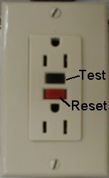
Figure 5.13. GFCI Receptacle.
The working principle is as follows: as long as the current in each conductor remains equal, the device remains in a closed position. If one of the conductors comes in contact with a grounded object, some of the current returns by an alternative path. The difference in the current that circulate through the conductors is sensed by a coil and the testing mechanism trips, disconnecting the output from the input.
GFCIs will not protect personnel from shock hazards where contact is between phase and neutral or phase-to-phase conductors.
According to the NEC® (Section 210.8), shall be installed for personnel protection in:
- Bathrooms
- Garages, and also accessory buildings that have a floor located at or below grade level not intended as habitable rooms and limited to storage areas, work areas, and areas of similar use. Exceptions are made of a ceiling-mounted receptacle installed for connection of a garage door opener or receptacle for appliances occupying a dedicated space.
- Outdoors, excepting not readily accessible and supplied by a dedicated circuit receptacle.
- Crawl spaces
- Unfinished basements
- Kitchens
- Wet bar sinks.
The panel schedule can be constructed from the electrical plan information, and may be prepared in the form shown in Figure 5.14.
| TYPE________________ PANEL - MAINS________________ | ||||||||||
| LOCATION________________ SECTION No____ BUS RATING_______________ | ||||||||||
| MOUNTING_______________ VOLTAGE_________________ | ||||||||||
| CKT | POLE/ | KVA | DESCRIPTION | WIRE | CKT | POLE/ | KVA | DESCRIPTION | WIRE & | |
| No. | TRIP | No. | TRIP | CONDUIT | ||||||
| 1 | 2 | |||||||||
| 3 | 4 | |||||||||
| 5 | 6 | |||||||||
| 7 | 8 | |||||||||
| 9 | 10 | |||||||||
| 11 | 12 | |||||||||
| 13 | 14 | |||||||||
| 15 | 16 | |||||||||
| 17 | 18 | |||||||||
| 19 | 20 | |||||||||
| 21 | 22 | |||||||||
| 23 | 24 | |||||||||
| 25 | 26 | |||||||||
| 27 | 28 | |||||||||
| 29 | 30 | |||||||||
| 31 | 32 | |||||||||
| 33 | 34 | |||||||||
| 35 | 36 | |||||||||
| 37 | 38 | |||||||||
| 39 | 40 | |||||||||
| 41 | 42 | |||||||||
Figure 5.14. Panel Schedule
4) Ranges:
- The minimum branch circuit for ranges 8 ¾ kW or more rating shall be 40 Amp. [Article 210.19(3)]
- For ranges individually rated more than 12 kW but no more than 27 kW, the maximum demand load (Table 220-19, column C) shall be increased 5% for each additional kW of rating or major fraction thereof by which the rating of individual ranges exceed 12 kW [Article 210-19, note1].
Example 5.4: Find out the necessary conductor for a single branch circuit that supplies the following loads
| Appliance |
Rating |
| One counter-mounted cooking unit | 8 kW |
| One wall-mounted oven | 10 kW |
| Total 18 kW |
This can be treated as one range. From Table 220-19, column C it is obtained that for one range not over 12 kW, the demand is 8 kW.
The total installed exceed 12 kW in: 18 – 12 = 6 kW
5%/kW x 6 = 30% increase
30% x 8 kW = 2.4 kW increase
8 kW + 2.4 kW = 10.4 kW
I = 10400/240 = 43.33 Amp
The wire size is a No. 8 Copper, THWN
5.8. REVIEW QUESTIONS
5.1. Explain how to determine the number of general lighting circuits.
5.2. How many 20A general lighting circuits would be needed to satisfy the “minimum” code requirements for a 3000 sq.
ft. Residence?
5.3. The two kitchen and one laundry circuits should be rated _______________amperes, ______________ volts, and wired with AWG
No.? __________________conductors.
5.4. Name three places where GFCI receptacle are required.
5.5. A garage door opener (must have-does not need) a GFCI protected circuit.
5.6. Explain what is meant by:
a) ground fault
b) short circuit
5.7. It is permitted to clamp telephone conductors to the electrical service entrance.
a) True b) False
5.8. A 200 Amp service entrance needs AWG conductors __________________, AWG ground conductor______________ and service entrance conduit __________________.
5.9. The grounding electrode should be buried under grade level __________________ft.
5.10. A 5000 W, 240 V heater has a current equal to ____________________Amp.
5.11. The power loss in Watts for a conductor that carries 30
Amp and has a voltage drop of 7 Volts is _________________________.
5.12. For a 3600 sq. ft. unit with the following loads:
1500 VA dishwasher
1000 VA disposal
8000 VA range
5000 VA W.H.
4500 VA dryer
8500 VA A/C
Calculate:
a) The feeder conductor size
b) The grounding copper conductor size
5.13. A 6000 Watts, 240V water heater has a current
of _________ Amp.
a) 21
b) 18 c) 30
d) 25
5.14. The wire size (AWG) required in question
(1) is:
a)14
b) 12 c) 10
d) 8
5.15. The maximum continuous load on an over current
protection device rated 100 Amp is:
a) 80 Amp
b) 88 Amp c) 90 Amp
d) 100 Amp
5.16. What is the power loss in watts for a conductor
that carries 30 Amp and has a voltage drop of 6 volts?
a) 180
b) 750 c) 200
d) 1020
5.17. Receptacle rated 15 Amp may be connected
to a 20 Amp multi-outlet branch circuit.
a) true
b) false
5.18. What changes AC to DC?
a) Transfomer
b) generator c) rectifier
d) none of these
5.19. A circuit with #12 THHN protected by a 15 O.C.P.
is a 20 Amp circuit.
a) true
b) false
5.20. Continuous loads shall not exceed _________
% of the branch circuit rating.
a) 125
b) 80 c) 75
d) a&b
5.21. Wiring methods permitted for service conductors include:
a) EMT
b) liquid tight c) MC cable
d) all of these
5.22. Rigid metal conduit can not serve as the main entrance
grounding conductor.
a) true
b) false
National Electrical Code® and NEC® are registered trademarks
of the National Fire Protection Association, Inc., Quincy, MA 02269