CHAPTER IV
AIR DISTRIBUTION AND BALANCE
4.1. INTRODUCTION
When projecting an air-conditioning system, the following steps should be followed:
1) Determine the heat gain or loss
2) Establish the air requirements (cfm) to remove or add air.
3) Design a duct system capable of distributing the required cfm.
4) Select a fan to move the quantified cfm against the calculated resistance of the system.
This chapter is devoted to steps 3 and 4.
4.2. AIR DISTRIBUTION SYSTEM
Cooling and heating systems use air to carry heat through all the facility. The quantity of heat to move and the temperature difference between room air and conditioned air determines the air that circulates through the ducts and other parts that compose the air distribution system. The air distribution system is composed of air handler, ducts and registers.
4.2.1 AIR HANDLER
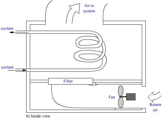
In compressive refrigeration cycles, the air handler is composed of the warm air input, that permits the return air to flow through the device; the filter that cleans the air; the evaporator coil that conveys the cool gas, which cools the circulating air; the fan that blows the air again inside the facility; the outdoor air intake (where it exists); and the output to the distribution ducts. Figure 4.1 shows schematic view of an air handler.


Figure 4.1. Air handler
4.2.2 REGISTERS
Registers are outlets that distribute and control conditioned air. They are composed of a diffuser that spreads out the air and a damper to control the air quantity.
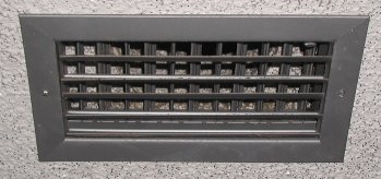
A good register selection will allow the distribution of the conditioned air without causing uncomfortable drafts. When distributing cool air, the registers should be located near to the ceiling, because the more dense cool air will tend to move down. When distributing warm air, the registers should be located near the floor because the warm air tends to move up. Figure 4.2 Shows a register

Figure 4.2. Register
Different registers have different air distribution patterns. The patterns for wall registers are straight, medium and maximum depending on the way the air will spread out in the room. Other factors in the wall register selection are the number of cubic feet per minute (cfm) and the horizontal distance the air stream travels from a register before it slows to a velocity comfortable for people (throw).
Ceiling diffusers provide throw distances for 1 way, 2 way opposite, 2 way corner, 3 way and 4 way. Floor registers should be selected for throw distances from the floor to the ceiling. The information for the register selection can be found in manufactures' catalogs or any other specialized catalogs.
4.2.3. DUCTS
The ducts serve as a carrier to convey the air used for heating or cooling. Most rectangular ducts are constructed using galvanized steel or fiberglass. Flexible round ducts are frequently used in residential installations.
The factors that affect the quantity of air that circulates per unit time (cfm) through the duct and its velocity (fpm) are the duct size and the fan power. The quantity of air that circulates per minute in a duct system is determined by the quantity of heating or cooling required and by the temperature difference between conditioned air and room air. The quantity in cubic feet per minute (cfm) can be calculated using formula (2.14), which is reproduced below:
![]()
where SH is the amount of sensible heat that must be added or removed to maintain the specified room temperature in BTUh and TD is the temperature difference in degrees Fahrenheit between the conditioned air and the room air.
Example 4.1. A room has a summer peak sensible heat gain of 20000 BTUh. How much 55 ºF air is required to maintain 75 ºF in the room?
cfm = 20000 / ( 1.08 x ( 75 - 55) ) = 925.9
Another way of calculating the cfm in a building is the following: having calculated the heat gain in the building, the total quantity of cfm can be calculated multiplying the total tons by 400. This is due to the assumption that air handlers typically circulate about 400 cfm for each ton of capacity. The cfm for each room in the building is calculated in proportion to floor area.
4.3 DUCT CALCULATIONS
The simplest way of calculating the duct size is using the duct friction chart. On this chart the cubic feet per minute, the velocity, the duct diameter and the friction loss in the duct are represented. Knowing two of this parameters, it is possible to find out the other two. A simplified version of the chart is shown in figure 4.3.

Figure 4.3. Duct Friction Chart, Range 1000 to 30000 cfm.
The recommended main ducts velocities are shown on Table 4.1.
| Application | Main Ducts |
| Residences | 1000 |
| Hotels and motels bedrooms | 1400 |
| Theatres and auditoriums | 1300 |
| General offices, quiet restaurants | 1900 |
| Industrial buildings | 2400 |
Table 4.1. Recommended Duct Velocities, fpm
Example 4.2. The sensible heat gain in a residence is calculated as 36000 BTUh. The conditioned air has a temperature of 55º F and the residence temperature is 75º F. Calculate the size of the main duct to be connected to the air handler.
The necessary cfm through the main duct are:
cfm = 36000/1.08(75-55) = 1667
The recommended velocity is 1000 fpm as per Table 4.1. From Figure 4.3, the duct size is approximately 18" round.
Frequently it is not convenient or desirable to use round ducts. In this case it is necessary to convert from round to rectangular ducts. For making the conversion, it is necessary to utilize a chart that gives the rectangular equivalents of round ducts. This chart may be found, for example in [1] or in some specialized manual.
4.4. EQUIVALENT LENGTHS OF ELBOW
When calculating the friction loss in a duct system, the result will make it convenient for you to find the equivalent length of elbows in order to simplify the calculations. Figure 4.4 shows an elbow, where the different participating parameters are presented.

Figure 4.4. Standard Radius Elbow

Figure 4.4. Standard Radius Elbow
The procedure to find out the elbow equivalent length is as follows:
a) Find R/W
b) Find H/W
c) Go to the elbow friction-loss chart shown on Figure 4.5 to find L/W
d) Multiply the L/W by the width of the elbow and divide by 12".

Figure 4.5. Elbow Friction-Loss Chart.
Example 4.3. Given an elbow 36" wide by 24" deep, and 20" radius, find the equivalent length of the elbow.

4.5. DUCT SYSTEM AND FAN CALCULATION
When sizing the ducts and the fan, the following steps should be followed:
1) Find the cfm in the main duct
2) Find the round duct diameter for each part of the system
3) If necessary, convert the round ducts to rectangular ducts
4) Solve for the elbow equivalent length
5) Calculate the total equivalent length
6) Determine the actual duct friction loss
7) Calculate the actual friction
8) Calculate the fan hp applying the formula
hp = (cfm x Fan Pressure) / 4000
Example 4.4. The air conditioning system shown on Figure 4.6 is installed in a small auditorium. For architectural and structural reasons, the ductwork must be held at an 18" height throughout. The run outs are 10' each. Pressure loss through the outlet is 0.07" WC. Pressure loss through the return, outside air duct and filter bank is 1.2" WC. The main duct will be rectangular, and the run outs will be round flexible ducts.

Figure 4.6 Duct System.
Solution:
1) Main Duct cfm = 1400 + 600 + 1000 = 3000
2) & 3) Round Ducts Diameter
The maximum duct velocity is found from Table 4.1 as 1300 fpm.
From Figure 4.3 (Duct Friction Chart), is obtained the friction loss as 0.1 inches of water per 100 feet. This will be the System design point for creating the following Table:
| CFM | RUN | Length | Round Duct | Rectangular
Equivalent |
| 3000 | AB | 60 | 21 | 18 x 22 |
| 1600 | BC | 40 | 17 | 18 x 13 |
| 1000 | CD | 30 | 14 | 18 x 9 |
| 1400 | B1 | 10 | 16 | |
| 600 | B2 | 10 | 11 | |
| 1000 | B3 | 10 | 14 |
4) Solve for the loss at elbow
Elbow at D --- (H/18) (W/9)
Radius Ratio: (R/W) = 1.5 (datum)
Aspect Ratio: (H/W) = (18/9) = 2
Length Ratio: (L/W) --- Chart --- (L/W) = 5
Equivalent Length: Leq= (5 x 9 ) / 12 = 3.75 ft
5) Total Equivalent Length
If the run outs are in parallel only the run out with the greatest pressure drop or longest equivalent length is entered.
| CFM | RUN | SIZE | Equivalent Length |
| 3000 | AB | 18 x 18 | 60 |
| 1600 | BC | 18 x 13 | 40 |
| 1000 | CD | 18 x 9 | 30 |
| 1000 | Elbowed | 18 x 9 | 3.75 |
| 1000 | B3 | 18 x 9 | 10 |
|
Total -- 143.75 ft. | |||
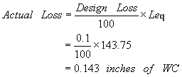
6) Actual Friction Loss

7) Total Friction

8) Fan horsepower
hp = (3000 x 1.413) / 4000 = 1.06
4.6 REVIEW QUESTIONS
4.1. The air volume moving through a duct is 100 cfm. The duct has a diameter
of 6”. Find:
a. velocity in fmp
b. pressure drop
4.2. In the figure below
A = 80 ft; B = 100 ft; C = 50 ft; D = 80
ft

For architectural and structural reasons, the ductwork must be held to a 15 inch height throughout. The runouts are each 40 ft. The fan outlet is 1500 fpm. Pressure loss through the last outlet is 0.07 in WG. Pressure loss through the return, outside air duct and filter bank is 1 in. WG.
a. size the ducts for: A, B, C, D, E, F, G, H
b. Find the
horsepower of the fan motor.
4.3. A system has a duct run handling 300 cfm of air inside a room. The total effective length is 170 ft. Let’s assume that the fan is capable of moving the correct air flow in the supply duct with a friction loss of 0.36 in. WG. Cooling coil loss = 0.24. Supply register loss = 0.03.
Find the duct diameter.