CHAPTER
II
HEAT GAIN AND
LOSS
2.1.
INTRODUCTION
The heat flows through the building’s skin, affecting its interior temperature. The basic components of the building envelope are the walls, roofs, floors, doors and windows. As it is known from the previous chapter, as the temperature difference increases between two surfaces of any object, the heat flow between these two surfaces will also increase. In order to diminish the heat flow in buildings, insulation is used. Insulation slows heat flow, but does not stop it. Frequently, internal air spaces are used in building’s envelopes to limit conducted heat flow. Another way of gaining or losing heat in a building is through the air that is forced or infiltrated to the building from the outside surroundings.
This chapter will give the basic knowledge to calculate the quantity of heat gained or lost in a building. This knowledge will enable the student to determine the size of the heating and cooling equipment.
2.2. HEAT TRANSFER
THROUGH WALLS
As it was presented in the previous chapter, the heat transfer through solids comply with the relation (1.4):
![]()
but also it was defined the resistance R=1/C, from which, the formula can be written as:
![]()
for walls with different layers, the total thermal resistance is obtained as the sum of all the layers’ resistance as can be seen from Figure 2.1.
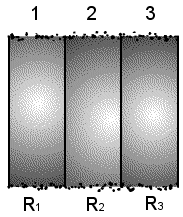
Figure 2.1. Wall
formed by three layers.
The total resistance will be:
R = R1 +R2 + R3
Example 2.1.
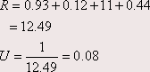
Calculate the resistance of a composite structure composed of a 2x4 stud wall with brick veneer, 3’’ of insulation and a dry wall interior.
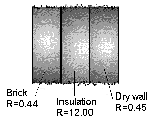
Figure 2.2. Composite wall.
![]()
In practical applications, the different construction materials are more or less standardized and their resistance values can be found in tables. As normally in construction, the building skins are composed of different layers and of different materials. For the case of walls with different layers it is useful to define another term known as U-Value.
The U-Values are calculated for a particular element (wall, door, roof, etc) by finding the resistance of each of its component materials, including air layers and adding all the resistance as:
![]()
The U-value is the reciprocal of the sum of resistances.
For a composite wall, the expression (2.1) can be also used, but using the total resistance. In Figure 2.1, it is possible to substitute the three layers by one equivalent with resistance:
![]()
the U-value will be:
![]()
and the heat flow
![]()
Example
2.2.
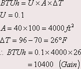
A building has a 40’x100’ flat roof, constructed on 4’’ gypsum slab on 1’’ glass fiber board. The interior ceiling is ¾’’ acoustical tile suspended on channel. The outside temperature is 96° F and the inside temperature is 70° F. The U-value obtained from the manual is 0.1. Calculate the heat gain or loss per hour by the building through the roof.
Example
2.3.
Calculate the U-value of the shown wall
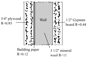
Figure 2.3. Composite wall for Example 2.3.
Example
2.4.
The figure shows one wall with a glass window in a house with the following specifications:
Wall material: wood sheathing, 2’’ of insulation with R-7 value, and inside finished. U=0.09 BTUh/ft2-°F. Window material: Single glass, aluminum frame. U=1.1 BTUh/ft2-°F. The temperature difference between inside and outside is 40° F.
Figure 2.4. Wall
for example 2.4.
The heat flow per hour is calculated independently for the wall and the window. Applying equation 2.5:
Wall:
![]()
Window:
![]()
The total heat transfer is:
![]()
2.3.
PARTICULAR CASES OF HEAT TRANSFER IN A BUILDING
In different situations, the heat transfer cannot be calculated directly by applying the equation 2.5, and some assumptions have to be made. Some of them are the following.
2.3.1. HEAT TRANSFER THROUGH BASEMENT WALLS AND FLOORS.
The fact that the basement floor and part of the entire wall is below grade complicates the calculations.
For the part of the structure which is below grade, the used U-values shall be in accordance with table 2.1.
Table 2.1 U-value for Basement walls and Floors Below Grades [BTUh/ft2-°F]
|
Material |
U-Value |
|
Wall, uninsulated --------------- |
0.16 |
|
Wall, R-4 insulation ------------ |
0.08 |
|
Floor -------------------------- |
0.04 |
This is due to the effect of the surrounding ground on the thermal resistance.
Also the temperature difference will be different. The outside winter design temperature is taken as the deep ground temperature value. This temperature range between 40°F and 60°F in cold climates in the continental United States.
If part of the basement wall is above ground and part is
below, the heat transfer loss for each situation is calculated separately.
Example
2.5.
A basement has a floor area of 400 ft2 and an insulated wall below ground of 640 ft2 area. The room temperature is 75°F and the ground temperature is 50°F. Find the heat lost from the room
Floor: BTUh = 0.04 x 400 x 25 = 400
Wall: BTUh = 0.08 x 640 x 25 = 1280
The total heat losses are:
![]()
2.3.2. HEAT TRANSFER THROUGH FLOOR ON GROUND AND FLOOR OVER CRAWL
SPACE.
For the floor constructed over crawl space, if the crawl space is ventilated to prevent moisture condensation, the crawl space air temperature will be equal to the outside air design temperature.
When the floor is in the ground in cold weather, the heat loss is greater throughout the building’s perimeter, and proportional to the perimeter length. In this case the heat transfer is calculated using the relation 2.6.
![]()
Where Q/t is the heat transfer loss through floor on grade in BTU/hr, P is the perimeter loss coefficient in BTU/h.ft-°F, L is the total perimeter length in ft, and DT is the design temperature difference between inside and outside in °F.
2.4.
INFILTRATION AND VENTILATION HEAT LOSS OR GAIN
In a building, the heat is not only lost or gained through
the walls, roof and floor. There is
a quantity of heat that comes inside or goes outside the building with the air
that circulates in or out of the building.
The two means by which air bring or take heat to or from the building
are called infiltration and
ventilation.
2.4.1. SENSIBLE HEAT LOSS OR GAIN EFFECT OF INFILTRATION OR VENTILATION AIR.
Infiltration occurs when outdoor air enters through building openings due to wind pressure. These openings may result from door edges, doors or windows openings, or cracks around windows.
Infiltration air entering a room in summer will increase the room temperature. In winter the effect is the opposite. This heat gained or extracted should be compensated in the room to maintain its design temperature.
The amount of heat required to maintain the room temperature is determined using the sensible heat equation represented in (1.4)
![]()
where Qs/t is the heat required to maintain the room temperature, mt is the weight flow rate of outdoor air infiltration in lb/hr, c is the specific heat of air, DT is the temperature change between outdoor and indoor air in °F.
The flow rate of air in HVAC works is usually measured in ft3/min (CFM), and the air flow rate in previous equation is expressed in lb/hr.
Therefore, it is necessary to realize the conversion. Including in the equation the specific heat of air, which is a constant, the final result will be
![]()
where Qs/t is the sensible heat from the infiltration (or ventilation) air; CFM is the Air infiltration (or ventilation) flow rate in ft3/min; and DT is the temperature difference between outdoor and indoor air in °F.
2.4.2. LATENT HEAT LOSS OR GAIN EFFECT OF INFILTRATION VENTILATION
AIR
Since the humidity of the outdoor air is frequently different from the indoor air humidity, this parameter may fall to an unacceptable level of comfort.
If the room air humidity is to be maintained, water vapor must be added or extracted. The change of moisture requires heat.
Therefore, heat of vaporization of water will be added or extracted. This is expressed by the equation.
![]()
where QL/t is the latent heat required for infiltration or ventilation air; CFM is the air infiltration or ventilation rate in ft3/min; and (W1 – W2) is the difference in humidity ratio between indoor and outdoor in grains water/lb.
A more detailed study of air properties will be made in chapter III.
To determine the quantity of infiltration air in a building, two methods are used: the crack method, that assumes that a reasonably accurate estimate of the rate of air infiltration per foot of crack opening can be measured or established, and the air change method. In this course the air change method will be used for calculating the heat gain or loss by the building due to the infiltration air.
The air change method is based on the number of air changes per hour (ACH) in a room caused by the infiltration, where one air charge is defined as being equal to the room air volume.
The determination of the expected number of air changes is based on experience and testing, and is different for different facilities, and given in tables.
To find out the CFM from the number of air changes per hour, the following relation should be used:
![]()
Where CFM is the air infiltration rate to room in ft3/min, ACH is the number of air changes per hour for the room, and V is the room volume in ft3.
Example 2.6.
A 30 ft x 12 ft x 8 ft high room is a house has 0.6 air
changes per hour due to infiltration.
Find out the infiltration rate in CFM.
V = 30 x 12 x 8 = 2880 ft3
Using equation (2.9)
![]()
2.4.3. VENTILATION
LOAD
The air that is brought into residential buildings through
the mechanical ventilation equipment in order to maintain the indoor air quality
is known as ventilation air. Air distributing systems in residences
almost always use re-circulated air only.
In this case there is no ventilation load component.
Non-residential buildings always use ventilation air. In this case, in the calculations, the
infiltration air load may be neglected.
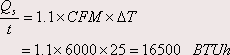
Example 2.7.
A building with sealed windows is maintained at 70°F, with an outdoor temperature of 95°F. The mechanical ventilation system introduces 6000 CFM of outside air. What is the additional sensible heating requirement for this effect?
2.5.
EFFECT OF THE
AIR FILM ON THE WALL
RESISTANCE
The air forms a film besides the wall that affect the total
heat resistance of the wall, increasing it. According to this, the heat transferred
through a wall must include the effect of convection at the inside and outside
surfaces. Table 2.2 shows the air
film resistance under different conditions.
Table 2.2. Air film Resistance.
|
|
Summer |
Winter |
|
|
7.5 mph wind |
15 mph wind |
|
Outside Surface |
0.25 |
0.17 |
|
Inside Surface |
0.68 |
0.68 |
Example 2.8
| The wall discussed in the Example 2.4 had a total resistance of 12.89 |
Find the total wall resistance for summer.
Outside air film resistance ---------------------- 0.25
Wall resistance --------------------------------- 12.89
Inside air film resistance ------------------------- 0.68
Net effective resistance -------------------------- 13.82
2.6.
EQUIVALENT TEMPERATURE DIFFERENCE (ETD)
The effect of the sun and thermal storage must be included when the heat gain through a wall, roof, or other component is calculated.
The ETD depends on orientation of the exposure, time of day,
and construction materials. The
procedure outlined in the ASHRAE Fundamentals Handbook is a simplified one, that
uses average ETDS which eliminate orientation and time of day.
A more complete table can be found on the ASHRAE manuals.
Table 2.3. Equivalent Temperature Difference.
|
Outdoor Design Temperature |
85° F |
90º F |
95º F | ||||||
|
Daily Temperature Range |
L |
M |
|
L |
M |
H |
L |
M |
H |
|
Walls and Doors |
|
|
|
|
|
|
|
|
|
|
Frame & Veneer on frame |
17.6 |
13.6 |
|
22.6 |
18.6 |
13.6 |
27.6 |
23.6 |
18.6 |
|
Wood Doors |
17.6 |
13.6 |
|
27.6 |
18.6 |
13.6 |
27.6 |
23.6 |
18.6 |
Daily Range:
L (Low) < 15º F
M (Medium) 15 to 25º F
H (High) > 25º F
The values on the table are based on average indoor temperature of 75°F.
The heat gain is calculated through the formula.
![]()
The daily range is the average difference between the daily high and the daily low temperature for a given location.
Table 2.4. Shows the daily range for several cities in the U.S.
|
City |
Daily Range |
|
Miami ------------------------ |
15 |
|
Atlanta ----------------------- |
19 |
|
Chicago, O' Hare (Airport) --- |
20 |
|
Boston (Airport) -------------- |
16 |
|
New York City (Central Park) - |
17 |
2.7.
HEAT GAIN THROUGH GLASS
In the summer, total heat gain through glass is equal to the
combined effects of solar radiation and transmission. The solar radiation varies
with month, time of day, direction the window is facing, number of panes, type
of glass, type of outdoor and indoor shading and the capacity of the building materials
to store heat.
- Air temperature difference across the glass.
-
Glass U
value.
For the heat gain calculation it is necessary to use the Heat Transfer Multiplier (HTM), defined as the amount of heat that flows through one ft2 of building envelope at a given temperature difference. Table 2.5. shows several HTM values, which are based on the average heat gain through glass that occurs in the warmest summer month over an hourly period that extends from mid morning through late afternoon. The use of this table does require to consider:
- Exposure
- Number of panes
- Type of glass
- Indoor shading
- Outdoor shading
Table 2.5. HTM through glasses
|
Regular Single Glass | |||
|
Outdoor Design Temperature |
85 |
90 |
95 |
|
No Awnings or Inside Shading | |||
|
N |
23 |
27 |
31 |
|
NE & NW |
56 |
60 |
64 |
|
E & W |
81 |
85 |
89 |
|
SE & SW |
70 |
74 |
78 |
|
S |
40 |
44 |
48 |
|
Horiz. Skylight |
160 |
164 |
168 |
Using Table 2.5, the heat gain through glass will be calculated by
![]()
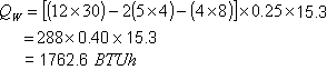
Example 2.9.
Calculate the heat gain for the following wall:
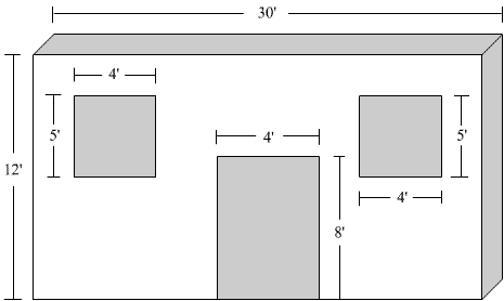
Wall: Masonry wall, 8 in. block. U value = 0.40
Door: Wood, slab in wood frame. U value = 0.48
Windows: Regular
single glass, no awning or inside shading
Location: Miami,
wall facing N. Assuming outside
design temperature: 90°F
Solution:
Wall: Daily temperature range: 15°F--- L
Outside T: 90°F------ETD = 15.3
Door:
![]()
Windows:
![]()
Heat Gain = 1762.6 + 199.7 + 1080 = 3042.3 BTUh
2.8.
HEAT INTERCHANGERS
The AC systems are based on the principle of heat interchange. The heat is extracted from inside the building, and delivered outside the building. Figure 2.5, shows the way the heat interchanger works. The substance intended to extract heat passes through a coil which is in intimate contact with the other substance at higher temperature. The substance at a higher temperature (Th) deliver heat that is absorbed by the flowing substance inside the coil, lowering the temperature Th and increasing the flowing substance temperature from Ti to Tf. The opposite situation is also possible.
The quantity of heat extracted can be calculated through the relation (2.12)
![]()
S.H --- Specific heat of circulating medium
TD --- Temperature difference between Ti and Tf
W --- Weight (mass) that circulates per unit time
Example
2.10.
Water is circulated through a water-cooled condenser at the rate of 10 gpm, entering condenser temperature is 65°F, leaving condenser temperature is 75°F. Find the BTUh and Tons of refrigeration. (1 gallon of water weighs 8.33 lb)
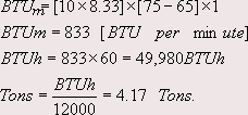
By making the correspondent calculations, it can be demonstrated that the following relations are true:
For Water:
![]()
For air:
![]()
Where gpm means gallons of water per minute, and cfm is the volume of circulating air in ft3 per minute.
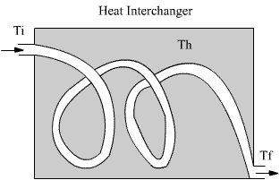
Figure 2.5. Heat
Interchanger
Example
2.11.
An air handler is moving 2000 cfm at an entering temperature
of 75° F and
leaving at 65° F. Find the
BTUh
BTUh = 1.08 x 2000 x 10
= 21605 BTUh
2.9. REVIEW QUESTIONS
2.1. The heat in a substance that can be felt or “sensed” by touch is called ________________ heat.
2.2. The amount of heat necessary to change the physical state of a substance is called _______________ heat.
2.3. At atmospheric pressure the quantity of heat required to convert 1 lb.
of 50ºF water to steam is:
2.4. The heat of evaporation of 1 lb. of water is equal to _______________________BTU.
2.5. Increasing temperature in an open system increases volatility and evaporation.
a) True b) False
2.6. Water expands and contracts with temperature changes.
a) True b) False
2.7. A water-cooled condenser rejects 260,000 BTUh total heat. Cooling
water enters at 72ºF and leaves at 83ºF. How many gallons are circulating
per minute?
2.8. A heating coil has a capacity of 300,000 BTUh when circulating 10gpm of water. If the leaving water temperature measures 150ºF, what is the entering water temperature?
2.9. The temperature of 100 lb. of dry air is raised from 75ºF to 165ºF, how many BTU are required?
2.10. Air air-cooled condenser rejects 140,000 BTUh total heat. Air enters
the condenser at 70ºF and leaves at 90ºF. How many cfm
are circulating?
2.11. A 40’ x 60’ wall is constructed on ½” gypsum board a 3 ½” mineral wool
and ¾” plywood. The temperature difference between the inside and outside
is 20ºF. Calculate the BTUh that circulate.