CHAPTER
VI
ELECTRICAL MOTORS
6.1. THREE-PHASE POWER
The material presented so far has dealt exclusively with single-phase alternating current and voltage, that is, with single sinusoidal sources. When dealing with relatively high power it is preferable to use three-phase power. This means to use an arrangement in which three sinusoidal voltages are generated out of phase with each other. The advantages of using this arrangement are basically three:
1) The weight of the conductors and other components in a three-phase system is much lower than in a single-phase system delivering the same amount of power.
2) The three-phase system can deliver constant power (not pulsing).
3) Three-phase motors have nonzero starting torque.
To begin the discussion of the three-phase power, consider a three-phase source connected in wye (or Y ) configuration, as shown in Figure 6.1.
Figure 6.1. Balanced three-phase AC circuit.
Each of the three voltages is 120o out of phase with the others, so that, referring to the neutral (central) point we may write:
va = Va max sin wt
vb = Vb max sin (wt + 120o)
vc = Vc max sin (wt - 120o)
A graph of these voltages vs time is shown in Figure 6.2.
Figure 6.2. Three-phase voltages as a function of time.
A phasor representation of theses voltages in a positive or abc sequence can be represented as shown in Figure 6.3, where the two axis are identified as Re (Real Axis), and Im (Imaginary Axis). A full understanding of this representation is only possible after studying complex numbers and is beyond the scope of this material. For the purposes of having an idea on how the phasor diagram work, it is possible to imagine that the three voltages are represented as three rotating vectors, that rotate counter clockwise with an angular velocity w rad/sec.
Figure 6.3. Positive sequence for balanced three-phase voltages.
In the circuit of Figure 6.1, the resistive loads are also wye-connected and balanced (i.e., equal). The voltages Va, Vb, and Vc taken with respect to the neutral node n, are called phase voltages and form balanced sets in the sense that
Va + Vb + Vc = 0
This statement is easily verified from the phasor diagram. Assuming that the voltages are numerically equal to a value V, it is possible to write
V – V cos 60o – V cos 60o = 0
A graphical solution is also possible.
The voltage difference from one line to the other is called line voltage (VL) and can be also calculated using the phasor diagram as shown on Figure 6.4 where two phase voltages Va and Vb were selected. Subtracting the two voltages it is possible to find the voltage difference, which is the line- voltage.
Figure 6.4. Vector addition of two phase-voltages
(VL)2 = (Va)2 + (Vb)2 – 2VaVb cos 120o
= V2 +V2 + 2V2 cos 60o
= V2 +V2 + 2V2 (1/2)
= 3V2
VL = Ö 3 V
This means that the line-voltage is 1.73 times greater than the phase-voltage.
Example: The line-voltage in a three-phase system is 480 Volts. Find the phase-voltage.
Vph = 480/1.73 = 277 Volts
The power delivered by each voltage source to the load is calculated by
Pa = (va) (i)
= (va)2/R
= (Vmax sin wt)2/R
= (Vmax)2/R sin2 wt
sin2 wt = (1 + cos 2wt)/2 and Vmax = Ö2 Veff
Pa = (Veff)2/R[1 + cos 2wt]
In this case Veff is the phase-voltage effective value represented as Vph.
Pa = (Vph)2/R[1 + cos 2wt]
For the other two phase-voltages the situation is similar, and the power delivered by each will be respectively:
Pb = (Vph)2/R[1 + cos( 2wt + 120o)]
Pc = (Vph)2/R[1 + cos( 2wt - 120o)]
The total power delivered is
P = Pa + Pb + Pc
= 3(Vph)2/R + 3(Vph)2/R[cos2wt + cos( 2wt + 120o) + cos( 2wt - 120o)]
But it is easy to demonstrate that
[cos2wt + cos( 2wt + 120o) + cos( 2wt - 120o] = 0
From where the three-phase power is obtained as
P = 3(Vph)2/R = const.
It is also possible to connect the three AC sources in a three-phase system in a so-called delta connection, although in practice this configuration is rarely used. What is frequently found is the balanced loads connected in a delta configuration, as shown in Figure 6.5. It should be noted that now the corresponding line-voltage appears across each impedance.
A characteristic of the loads connected in delta is that they draw 3 times as much current (and therefore absorb 3 times as much power) as a wye load with the same branch impedance.
Figure 6.5. Balanced wye generators with balanced delta loads
6.2. –MOTOR WIRE CIRCUIT SELECTION
Motors are devices that convert the electrical energy into mechanical energy. A big range of motors and applications can be found in the market. Articles 430 and 440 of the NEC® define the conditions of installation of motors. In the market can be found the following types of motors:
- Direct current motors
- Single-phase alternating current squirrel cage motors
- Polyphase alternating current motors
- Wound-rotor three-phase motors
- Synchronous motors
- Step motors
The basic information about the motor characteristics is obtained from the nameplate. Figure 6.6 shows a motor nameplate.

Figure 6. 6. Motor nameplate
The following information is obtained from the nameplate:
- Frame and type. The NEMA designation for frame designation and type
- Horsepower. The power rating of the motor
- Motor code. Designated by a letter indicating the starting current required
- Frequency. The number of hertz at which the motor is designed to be operated
- Phase. The number of phases on which the motor operates
- RPM. The number of revolutions per minute of the motor at full load
- Voltage. The voltage or voltages of operation
- Thermal protection. An indication of the thermal protection provided for the motor if it has any
- Amps. The rated current in amperes at full load
- Duty. The time rating of the motor showing the duty rating as continuous or as specific period of time the motor can be operated
- Ambient temperature, or temperature rise. The maximum ambient temperature at which the motor should be operated, or the permissible temperature rise of the motor above the ambient air at rated load
- Service factor. The amount of overload that the motor can tolerate on a continuous basis at rated voltage and frequency
- Insulation class. A designation of the insulation system used
- NEMA design. A letter designation for integral horsepower motors specifying the motor characteristics
Motor Circuit Conductors
There are three common motor circuits:
- Single motor
- Multiple motor
- Motor and other loads
- Hermetic compressor motor circuit (Covered in the Article 440 of the NEC® (Air Conditioning and Refrigerating Equipment).
The conductors that supply a single motor used in a continuous duty application shall not be less than 125% of the full-load ampere rating of the motor (Section 430-22 NEC®). The full-load current for each motor is obtained from the corresponding table in Article 430 of the NEC®. Partial reproductions of Tables 430-148 and 430-150 are shown on Figures 6.7 and 6. 8.
| Horsepower | 115 Volts | 200 Volts | 208 Volts | 230 Volts |
| 1/6 | 4.4 | 2.5 | 2.4 | 2.2 |
| ¼ | 5.8 | 3.3 | 3.2 | 2.9 |
| 1/3 | 7.2 | 4.1 | 4.0 | 3.6 |
| ½ | 9.8 | 5.6 | 5.4 | 4.9 |
| ¾ | 13.8 | 7.9 | 7.6 | 6.9 |
| 1 | 16 | 9.2 | 8.8 | 8.0 |
| 1½ | 20 | 11.5 | 11.0 | 10 |
| 2 | 24 | 13.8 | 13.2 | 12 |
| 3 | 34 | 19.6 | 18.7 | 17 |
| 5 | 56 | 32.2 | 30.8 | 28 |
| 7½ | 80 | 46.0 | 44.0 | 40 |
| 10 | 100 | 57.5 | 55.0 | 50 |
Figure 6.7. Full-Load current in Amperes, Single-Phase Alternating current motors
( From Table 430-148, NEC®)
Reprinted with permission from NFPA 70-1999, the National Electrical Code®, Copyright© 1998, National Fire Protection Association, Quincy, MA 02269. This reprinted material is not the referenced subject which is represented only by the standard in its entirety.
| Horsepower | 115 Volts | 200 Volts | 208 Volts | 230 Volts | 460 Volts |
| ½ | 4.4 | 2.5 | 2.4 | 2.2 | 1.1 |
| ¾ | 6.4 | 3.7 | 3.5 | 3.2 | 1.6 |
| 1 | 8.4 | 4.8 | 4.6 | 4.2 | 2.1 |
| 1 ½ | 12.0 | 6.9 | 6.6 | 6.0 | 3.0 |
| 2 | 13.6 | 7.8 | 7.5 | 6.8 | 3.4 |
| 3 | -- | 11.0 | 10.6 | 9.6 | 4.8 |
| 5 | -- | 17.5 | 16.7 | 15.2 | 7.6 |
| 7 ½ | -- | 25.3 | 24.2 | 22 | 11 |
| 10 | -- | 32.2 | 30.8 | 28 | 14 |
| 15 | -- | 48.3 | 46.2 | 42 | 21 |
| 20 | -- | 62.1 | 59.4 | 54 | 27 |
| 25 | -- | 78.2 | 74.8 | 68 | 34 |
| 30 | -- | 92 | 88 | 80 | 40 |
| 40 | -- | 120 | 114 | 104 | 52 |
| 50 | -- | 150 | 143 | 130 | 65 |
Figure 6.8. Full-Load Current Three-Phase Alternating-Current Motors. Induction Type Squirrel Cage and Wound Rotor (Amperes). From Table 430-150, NEC®
Reprinted with permission from NFPA 70-1999, the National Electrical Code®, Copyright© 1998, National Fire Protection Association, Quincy, MA 02269. This reprinted material is not the referenced subject which is represented only by the standard in its entirety.
Where two or more motors are used together or where one or more motors are used in combination with other loads, such as resistance heaters, etc the conductors supplying this load shall have an ampacity at least equal to the sum of the full-load current ratings of all the motors, plus 25% of the highest rated motor in the group, plus the ampere rating of other loads.
Example 6.1. Find the wires needed for feeding a 3 hp,240 Volts, single-phase motor.
- From Figure 6.7: I = 17 Amps.
- The calculated value will be: 1.25 x 17 = 21.25 Amps.
- From Figure 3. 15: the necessary wire is a # 10 copper wire
Example 6.2. Find the feeder size for feeding three 460 Volts, three-phase motors with 10, 15, and 20 horsepower respectively.
|
Horsepower |
Full-load current |
| 10 | 14 |
| 15 | 21 |
| 20 | 27 |
|
Total current = 62 |
|
| Calculated current = 62 + 0.25(27) = 68.75 Amps | |
From Figure 3. 15: the necessary wire is a # 4 THWN Copper wire
Voltage DropIf the motor is located far from the panel, the voltage drop in the conductor feeding the motor may reach some value that affect the motor work. Frequently the allowed voltage drop in the branch circuit cannot be higher than 3% to 5% of the motor name plate voltage. Because of this, the branch circuit wire size selected according to the studied rules might not be enough, and it is necessary to move to a bigger size. This will be clear with the following example.
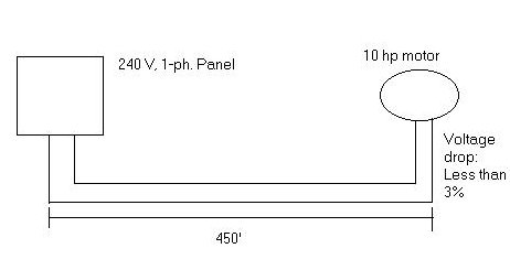
Example 6.3. Calculate the branch motor circuit size for the motor shown in Figure 6.9. The motor nameplate characteristics are as follows: single phase, 230 V, 10 HP. The maximum allowable voltage drop in the conductors is 5% of the nameplate voltage.
Figure 6.9. Motor Circuit.
According to Table 430-148, NEC® (fig. 6.7), this motor consumes 50 Amp. The necessary wire ampacity is 50 x 1.25 = 62.5 Amp. The selected copper wires are two # 6 THHN. From Table 8, NEC® the resistivity of this wire is 0.51 ohm/1000 ft.
The total resistance in the conductors will be: R = 0.51 x 800/1000 = 0. 408 W.
The voltage drop is: V = 0.408 x 50 = 20.4 Volts.
The maximum permitted voltage drop is: 230 x 0.05 = 11.5 Volts.
The selected wire size cannot be used because the actual voltage drop is higher than the permitted. Then it is necessary to use a bigger wire.
If two # 4 Cu. Wires are used, The total resistance is 0.32 x 800/1000 = 0.25W, and the voltage drop 0.25 x 50 = 12.5 Volts.
Using two # 3 THHN Cu. Wires:
R = 0.24 x 800/1000 = 0.19 W
V = 0.19 x 50 = 9.5 Volts.
Due to the distance, it is necessary to use two # 3 Cu. Wires for this motor.
6.3. OVERCURRENT PROTECTION
In a single motor circuit, the essential parts are: the branch-circuit conductors, the disconnecting means, the branch-circuit short-circuit and ground-fault protective devices, and the motor overload protective devices.
The branch-circuit short-circuit and ground-fault protective device may be a fuse or a circuit breaker and is required to be capable of carrying the starting current of the motor without opening the circuit. The motor branch-circuit, short-circuit and ground-fault protection is treated in part D of Article 430, NEC®. There are specified devices intended to protect the motor branch –circuit conductors, the motor control apparatus and the motors against over-current due to short-circuits or grounds for motors under 600 Volts.
The maximum values for the protective devices are shown in Figure 6.10 which is a partial reproduction of Table 430-152, NEC®.
|
Percentage of Full-Load Current |
||||
| Type of Motor | Nontime Delay Fuse | Dual Element (Time-Delay) Fuse | Instantaneous Trip Breaker | Inverse Time Breaker |
| Single-phase motors | 300 | 175 | 800 | 250 |
|
AC polyphase motors other than wound-rotor |
||||
|
Squirrel cage Other than Design E |
300 | 175 | 800 | 250 |
| Design E | 300 | 175 | 1100 | 250 |
Figure 6.10.. Maximum Rating or Setting of Motor Branch-Circuit Short-Circuit and Ground-Fault Protective Devices (Table 430.52 NEC).
Reprinted with permission from NFPA 70-1999, the National Electrical Code®, Copyright© 1998, National Fire Protection Association, Quincy, MA 02269. This reprinted material is not the referenced subject which is represented only by the standard in its entirety.
Figure 6.11 shows the essential elements in a single motor circuit.
Figure 6.11 A motor branch circuit showing the essential parts: branch-circuit conductors, disconnecting means, branch-circuit over-current protection, and motor overload devices.
6.4. REVIEW QUESTIONS
6.1. What are the advantages of the three-phase power?
6.2. In a WYE connection, if the phase voltage is 120 Volt. Calculate
the line voltage.
6.3. Calculate the power dissipated by a three-phase load for Vph = 120
Volt and RL = 50 ohms.
6.4. Enumerate three types of motors.
6.5. The greatest allowable voltage drop for a 1 hp, 120 V, 3 phases motor
is 10% of the name plate. The motor is located 250 ft. apart from the panel.
Find the needed wire.
6.6. The NEC® requires that motors shall be supplied by branch circuit
conductors having _________% of full-load current.
6.7. Find the circuit conductors supplying a 20 hp, 230 V, 3
phases squirrel-cage
motor.
6.8. Three resistive balanced loads are connected to a 480 Volt (line
voltage), 3-phase circuit.
What is the total power of the circuit in kW for a 40 Amp current?
6.9. In a motor nameplate, the label FLA means ______________________________.
6.10. In a motor nameplate the label SF means _______________________________.
6.11. The following loads are connected to a feeder: one 1
phase, 240 V, 5
hp motor, one 1 phase; 240 V, 3 hp motor and 10 amp receptacles/lights.
Find the feeder needed wire.
6.12. Calculate the wire size for the following installation:
6.13. A pump station has a 10 kVA lighting load, one 3 hp. motor, two 5 hp motors and one 15 hp motor (all 3 phases). All the loads are fed from a delta 3 ph., 240 V source, as shown in the Figure below.
a) Draw a circuit representing the motors and lights connected to the
source, including all the switches and over-current devices needed.
b) Find the load for each feeder and the protection devices rating.
National Electrical Code® and NEC® are registered trademarks
of the National Fire Protection Association, Inc., Quincy, MA 02269