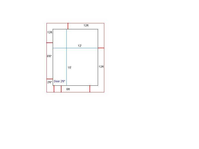
TABLE OF CONTENTS
Introduction
Floor Plan
Floor Plan w/ Dimensions
Electrical Plan
Residential Wiring Calculations
Wiring, Breaker, Junction Box and Conduit Calculations
Panel A
Panel B
Typical 120 V / 240 V; 150 A; Single Phase Riser
Typical Residential Riser; Main and Grounding for 120V / 240 V Single
Typical Residential Overhead Service
Typical 120 V / 240 V ; Single Phase Main Panel
Above Ground Minimum Clearance for Overhead Electrical Wires
Excerpt from Residential Wiring Code ( NEC 1996 )
Excerpt for Conduits ( NEC 1996 )
Electrical Symbols
Table 370-16 ( Allowance Ampacities of Insulated COnductors...)
Table 370-16 (a) ( Metal Boxes - Min.Cu.In. capacity )
Table 370-16 (b) ( Volume Required per Conductor ) - NEC 1996
Table 240-6 ( Standard Ampere Ratings ) - NEC 1996
Notes to Ampacity Tables of 0 to 2000 Volts - NEC 1996
Table 250-94 ( Grounding Electrode Conductor for AC Systems )
Table 250-95 ( Min. Size Equip. Grounding Conductors...) - NEC 1996
Table 4 ( Dimensions & Percentage Area of Conduit & Tubing
)
Table 5 ( Dimensions of Insulated Conductors & Fixture wires )
- NEC
Table 8 ( Conductor Properties )
Table 430-148 ( Full-load Current in Amps, Single Phase Ac Motors )
Table 430-150 ( Full-load Current 3 Phase AC Motors ) - NEC 1996
Table 430-152 ( Max. Rating or Setting of Motor Branch Circuit...)
NEC
Motors & Motor CIrcuits ( Name Plate info ) - H.Holzman
Table 430-7 (b) ( Locked Rotor Indicating Code Letters ) - Nec 1996
Typical Wiring for 4 Wire, 3 Phase, 230 V Source w/ 3 Phase Motor Load
& Lighting Load
Table 220-3 (b) ( General Lighting Loads by Occupancies ) - NEC 1996
This is an Electrical Remodeling of an existing residence.
Residence was built on/or about 1948 and Main panel did not have the
capacity for the additional load required.
Existing Main was for 100A and the new load required a NEW 150A service.
The reason for the increase over the old Main was:
Requirement for Service Disconnect @ Main Panel
New Electrical Range with a greater power consumption
New Central A/C
New appliances: Dishwasher
Garbage Disposal
Microwave
Clothes Dryer
Sprinkle Pump
Additional Refrigerator
Hence, a New Main was added inside the garage and the old Main became
a sub panel ( panel B ) for the New Main panel ( Panel A ).
The load was distributed where:
Panel A Sub feed to Panel B
A/C Compressor & Air Handler
Water Sprinkler Pump
Clothes Dryer
Washing Machine
Additional Refrigerator
Exterior Lights and Receptacles
Garage Lights and Receptacles
Panel B Range
Refrigerator
Dishwasher
Microwave
Garbage Disposal
2 Small Appliance Circuits
Lights and Receptacles for Inside the house
Front Exterior Light
| Give : | 2,230 sq.ft. home | 6.7 Kw [( 2230 sq.ft. )*( 3 w/sq.ft.)] |
| Range | 9 Kw | |
| A/C | 12 Kw | |
| Clothes Dryer | 6 Kw | |
| Water Heater | 5 Kw | |
| Garbage Disposal | 0.8 Kw |
| DESCRIPTION | VA ( Kw ) |
| General Lighting | 6,700 |
| Range | 9,000 |
| Garbage Disposal | 800 |
| Refrigerator # 1 | 1,500 |
| Refrigerator # 2 | 1,500 |
| 2 Small Appliance Circuits | 3,000 |
| Dishwasher | 1,000 |
| Water Heater | 5,000 |
| Clothes Dryer | 6,000 |
| Sprinkler Pump | 2,400 |
| Laundry ( Washing Machine ) | 1,500 |
| Total : | 38,400 |
| 1st 10 Kva @ 100 % | 10,000 |
| Bal. @ 40 % (28400 * 40 ) | 11,360 |
| A/C load @ 100 % | 12,000 |
| Total Load | 33,360 |
I = P / V = 33360 / 240 = 139.0 Amp
NOTE: If I < 150 Amp USE 150 A
RISER: 3 # 1 THWN Cu Wires in 1 1/2 " Rigid Metallic
Conduit
1 # 6 Grounding Cu Wire, Mechanically protected
FORMULAS
| To Determine Amperes needed | VA / V = Amps |
| To Determine Wiring Use: | Table 310-16 (1996 NEC ) |
| To Determine Fuses & Fixed
Circuit Breakers Use: |
Table 240-6 ( a ) ( 1996 NEC ) |
| To Determine Dimension of
Insulated Conductors & Fixture Wiring Use |
Table 5, 1995 NFPA |
| To Determine Dimensions &
Percentage Area of Conduit & Tubing Use: |
Table 4, 1995 NFPA |
| To Determine # of Wiring in
Tubing ( then match number from formula to Table 4, NFPA ) or, Use: |
[ ( Area of Wires ) / ( Percentage Area ) ]
Appendix C, Table C-1 (1999 NEC ) Conduit & Fill Tables for Conduits & Fixtures of the Same Size |
| To Determine Volume of Wires | Use: Table 370-16 ( b ) ( 1996 NEC ) |
| To Determine Size of Metal Box | Use: Table 370-16 ( a ) ( 1996 NEC ) |
| To Determine Amps in Single Phase Motors Use: | Table 430-148, 1996 NEC |
| Then for Current Calculation apply 125 % factor | I = ( 125 % ) * ( Amps ) |
| To Determine if wires will carry power NEED: | D = Distance of Motor from Panel
Ohms / Kft for AWG Wire Size see: ( @ Table 8, 1996 NEC ) Amps ( Table 430-148 1996 NEC ) Max. Voltage Drop Percentage ( % ) = V drop = ( Volts ) * ( Voltage Drop % ) = Volts' p (AWG Wire Size ) = [(ohms / Kft ) / 1000' ] * (# wires) * (D) = Ohms Vdrop (AWG Wire Size ) = (Ohms)*(Amps) = Volts IF < Volts' Wire OK |
NOTE: Not with standing Table - 310-16 ( Allowance
Ampacities of Insulated Conductors...)
In Normal Installations; Maximum are as follows for:
# 14 Cu wire up to 15 A max.
# 12 Cu wire up to 20 A max.
# 10 Cu wire up to 30 A max.
For Electric Disconect/Sub Feed to Panel B ( @ Garage ) ( Panel
A )
Electric Disconect/Sub Feed to Panel B 24 Kva
24000 va / 240 v = 100 A
Req'd. 100 A over current Device
( NEC Table 310 - 16 ) 3 # 3 THHN Cu Wires (
2 Hot, 1 Neutral )
Electric Disconnect / Sub Feed to Panel B 3 # 3 THHN Cu Wires
#3 THHN size Area = 0.0973 sq.in. (
Table 5, 1995 NFPA )
( 3 ) * ( 0.0973) = 0.2919 sq.in.
(0.2919 ) / 40 % = 0.730 sq.in. (
Table 4, 1995 NFPA; 2 + wires )
1 '' rigid metallic tubing area = 0.864 > 0.730
( Table 4, 1995 NFPA )
1'' Trade Size Conductor = 3 # 3 THHN ( App.
C, Table C1, 1999 NEC )
USE 1 '' Rigid Metallic
Tubing
No NEED for Box size
- Wires go directly to Sub Panel B
For Clothes Dryer ( @ Garage ) ( Panel A )
Clothes Dryer 6 Kva
6000 va / 240 v = 25 A
Req'd. 30 A over current Device
( NEC Table 310 - 16 ) 3 # 10 THHN Cu Wires (
2 Hot, 1 Neutral )
( NEC Table 250 - 95 ) 1 # 10 THHN Cu Grounding
Wire
Clothes Dryer 4 # 10 THHN Cu Wires
# 10 THHN size Area = 0.0211 sq.in. (Table
5, 1995 NFPA)
[( 4 )*(0.0211 )] = 0.0844 sq.in.
( 0.0844 ) / 40 % = 0.211 sq.in.
( Table 4, 1995 NFPA; 2+wires )
( 2.5 cu.in. )*( 4 ) = 10 cu.in. (
Table 370 - 16 (b); # 10 = 2.5 cu.in. )
1/2 '' rigid metallic tubing area = 0.304 > 0.211
( table 4, 1995 NFPA )
1/2 '' Trade Size Conductor = 5 # 10 THHN ( App.
C, Table C1, 1999 NEC )
USE 1/1 '' Rigid Metallic
Tubing
USE 4 x 1 1/4 Square
Box
Water Heater 4 # 10 Thhn Cu Wires
# 10 THHN size Area = 0.0211 sq.in.
(Table 5, 1995 NFPA)
[(4)*(0.0211)] = 0.0844 sq.in.
(0.0844) / 40% = 0.211 sq.in. (Table
4, 1995 NFPA; 2+wires)
(2.5 cu.in.)*(4) = 10 cu.in. (Table
370-16 (b); #10=2.5 cu.in.)
1/2" rigid metallic tubing area = 0.304 > 0.211
(Table 4, 1995 NFPA)
1/2" Trade Size Conductor =
5 #10 THHN (App.C, Table C1, 1999 NEC)
4 x 1 1/4 Square box = 18 cu.in. = 7 #10
(Table 370-16 (a); 1996 NEC)
USE
1/2" Rigid Metallic Tubing
USE 4 x 1 1/4 Square Box
For Range (@ Kitchen) (Panel B)
Range
9 Kva
9000va / 240v = 37.5A
Req'd.50A
over current Device
( NEC Table 310-16 ) 3 #8 THHN Cu Wires (2 Hot, 1 Neutral)
( NEC Table 250-95 ) 1 #10 THHN Cu Grounding Wire
Range
3 #8 THHN Cu Wires + 1 #10 THHN Cu Wire
#8 THHN size
Area = 0.0366 sq.in. (Table 5,
1995 NFPA)
#10 THHN size
Area = 0.0211 sq.in. (Table 5, 1995 NFPA)
[(3)*( 0.0366 )] + [ (1) * ( 0.0211)] = 0.1309 sq.in.
( 0.1309 ) / 40% = 0.0327 sq.in.
(Table 4, 1995 NFPA; 2+wires)
[(3)*(3 cu.in)] + [(1)*(2.5 cu.in)] =11.5 cu.in. (Table
370-16(b), 1996 NEC)
3/4" rigid metallic tubing area = 0.533 > 0.327
(Table 4, 1995 NFPA)
3/4" Trade Size Conductor =
6 #8 THHN (App. C, Table C1,1999 NEC)
4 x 1 1/4 Square box = 18.0 cu.in. = 6 38
(Table 370-16(a); 1996 NEC)
USE 3/4" Rigid Metallic Tubing
USE 4 x 1 1/4 Square Box
Laundry / Washing Machine 2 # 12 thhn cu Wires
# 12 THHN size Area = 0.0133 sq.in.
( Table 5, 1995 NFPA )
[( 2 )*( 0.0133 )] = 0.0266 sq.in.
( 0.0266 ) / 40 % = 0.0665 sq.in.
( Table 4, 1995 NFPA; 2+wires )
( 2 )*( 2.25 cu.in. ) = 4.5 cu.in. (
Table 370 - 16 (b); 1996 NEC )
1/2 '' rigid metallic tubing area = 0.304 > 0.0665
( Table 4, 1995 NFPA )
1/2 '' Trade Size Conductor = 9 # 12 THHN ( App.
C, Table C1, 1999 NEC )
4 x 1 1/4 Square box = 18.0 cu.in. = 8 # 12
( Table 370 -16(a); 1996 NEC )
USE
1/2 '' Rigid Metallic Tubing
USE
4 x 1 1/4 Square Box
For Refrigerator ( # 2 ) - ( @ Garage )
( Panel A )
Refrigerator 1.5 Kva
1500va / 120v = 12.5 A
Req'd.
20A
over current Device
(
NEC Table 310 - 16 ) 2 # 12 THHN Cu Wires ( 1 Hot, 1 Neutral )
Refrigerator 2 # 12 thhn cu Wires
# 12 THHN size Area = 0.0133 sq.in.
(
Table 5, 1995 NFPA )
[( 2 )*( 0.0133 )] = 0.0266 sq.in.
( 0.0266 ) / 40 % = 0.0665 sq.in. (
Table 4, 1995 NFPA; 2+wires )
( 2 )*( 2.25 cu.in. ) = 4.5 cu.in. (
Table 370 - 16 (b); 1996 NEC )
1/2 '' rigid metallic tubing area = 0.304 > 0.0665
( Table 4, 1995 NFPA )
1/2 '' Trade Size Conductor = 9 # 12 THHN ( App.
C, Table C1, 1999 NEC )
4 x 1 1/4 Square box = 18.0 cu.in. = 8 # 12
( Table 370 -16(a); 1996 NEC )
USE
1/2 '' Rigid Metallic Tubing
USE 4 x 1 1/4 Square Box
Refrigerator 2 # 12 thhn cu Wires
# 12 THHN size Area = 0.0133 sq.in.
( Table 5, 1995 NFPA )
[( 2 )*( 0.0133 )] = 0.0266 sq.in.
( 0.0266 ) / 40 % = 0.0665 sq.in. (
Table 4, 1995 NFPA; 2+wires )
( 2 )*( 2.25 cu.in. ) = 4.5 cu.in.
( Table 370 - 16 (b); 1996 NEC )
1/2 '' rigid metallic tubing area = 0.304 > 0.0665
( Table 4, 1995 NFPA )
1/2 '' Trade Size Conductor = 9 # 12 THHN ( App.
C, Table C1, 1999 NEC )
4 x 1 1/4 Square box = 18.0 cu.in. = 8 # 12
( Table 370 -16(a); 1996 NEC )
USE 1/2 '' Rigid Metallic Tubing
USE 4 x 1 1/4 Square Box
For Small Appliance ( # 1 & # 2 ) -
( @ Kitchen ) ( Panel B )
Small Appliance ( Each ) 1.5
Kva
1500va / 120v = 12.5 A
Req'd.
20A over current Device
(
NEC Table 310 - 16 ) 2 # 12 THHN Cu Wires ( 1 Hot, 1 Neutral )
Small Appliance ( Each ) 2 # 12 THHN Cu Wires
# 12 THHN size Area = 0.0133 sq.in.
( Table 5, 1995 NFPA )
[( 2 )*( 0.0133 )] = 0.0266 sq.in.
( 0.0266 ) / 40 % = 0.0665 sq.in. (
Table 4, 1995 NFPA; 2+wires )
( 2 )*( 2.25 cu.in. ) = 4.5 cu.in.
( Table 370 - 16 (b); 1996 NEC )
1/2 '' rigid metallic tubing area = 0.304 > 0.0665
( Table 4, 1995 NFPA )
1/2 '' Trade Size Conductor = 9 # 12 THHN ( App.
C, Table C1, 1999 NEC )
4 x 1 1/4 Square box = 18.0 cu.in. = 8 # 12
( Table 370 -16(a); 1996 NEC )
USE 1/2 '' Rigid Metallic Tubing
USE 4 x 1 1/4 Square Box
Microwave 2 # 14 THHN Cu Wires
# 14 THHN size Area = 0.0097 sq.in.
( Table 5, 1995 NFPA )
[( 2 )*( 0.0097 )] = 0.0194 sq.in.
( 0.0266 ) / 40 % = 0.0485 sq.in. (
Table 4, 1995 NFPA; 2+wires )
( 2 )*( 2 cu.in. ) = 6 cu.in.
( Table 370 - 16 (b); 1996 NEC )
1/2 '' rigid metallic tubing area = 0.304 > 0.0665
( Table 4, 1995 NFPA )
1/2 '' Trade Size Conductor = 12 # 14 THHN (
App. C, Table C1, 1999 NEC )
4 x 1 1/4 Square box = 18.0 cu.in. = 9 # 14
( Table 370 -16(a); 1996 NEC )
USE 1/2 '' Rigid Metallic Tubing
USE 4 x 1 1/4 Square Box
For Garbage Disposal - ( @ Kitchen ) ( Panel
B )
Garbage Disposal 0.8
Kva
800va / 120v = 6.67 A
Req'd.
15A over current Device
(
NEC Table 310 - 16 ) 2 # 14 THHN Cu Wires ( 1 Hot, 1 Neutral )
Garbage Disposal 2 # 14 THHN Cu Wires
# 14 THHN size Area = 0.0097 sq.in.
( Table 5, 1995 NFPA )
[( 2 )*( 0.0097 )] = 0.0194 sq.in.
( 0.0266 ) / 40 % = 0.0485 sq.in. (
Table 4, 1995 NFPA; 2+wires )
( 2 )*( 2 cu.in. ) = 6 cu.in.
( Table 370 - 16 (b); 1996 NEC )
1/2 '' rigid metallic tubing area = 0.304 > 0.0665
( Table 4, 1995 NFPA )
1/2 '' Trade Size Conductor = 12 # 14 THHN (
App. C, Table C1, 1999 NEC )
4 x 1 1/4 Square box = 18.0 cu.in. = 9 # 14
( Table 370 -16(a); 1996 NEC )
USE 1/2 '' Rigid Metallic Tubing
USE 4 x 1 1/4 Square Box
Dishwasher 2 # 12 THHN
Cu Wires
# 12 THHN size Area = 0.0133 sq.in.
( Table 5, 1995 NFPA )
[( 2 )*( 0.0133 )] = 0.0266 sq.in.
( 0.0266 ) / 40 % = 0.0665 sq.in. (
Table 4, 1995 NFPA; 2+wires )
( 2 )*( 2.25 cu.in. ) = 4.5 cu.in. (
Table 370 - 16 (b); 1996 NEC )
1/2 '' rigid metallic tubing area = 0.304 > 0.0665
( Table 4, 1995 NFPA )
1/2 '' Trade Size Conductor = 9 # 12 THHN ( App.
C, Table C1, 1999 NEC )
4 x 1 1/4 Square box = 18.0 cu.in. = 8 # 12
( Table 370 -16(a); 1996 NEC )
USE 1/2 '' Rigid Metallic Tubing
USE 4 x 1 1/4 Square Box
For Lights / Receptacles - ( Panel a &
Panel B )
Lights / Receptacles
1.2 Kva
1200va / 120v = 10.0 A
Req'd. 20A over current
Device
(
NEC Table 310 - 16 ) 2 # 12 THHN Cu Wires ( 1 Hot, 1 Neutral )
Lights / Receptacles 2
# 12 THHN Cu Wires
# 12 THHN size Area = 0.0133 sq.in.
( Table 5, 1995 NFPA )
[( 2 )*( 0.0133 )] = 0.0266 sq.in.
( 0.0266 ) / 40 % = 0.0665 sq.in. (
Table 4, 1995 NFPA; 2+wires )
( 2 )*( 2.25 cu.in. ) = 4.5 cu.in.
( Table 370 - 16 (b); 1996 NEC )
1/2 '' rigid metallic tubing area = 0.304 > 0.0665
( Table 4, 1995 NFPA )
1/2 '' Trade Size Conductor = 9 # 12 THHN ( App.
C, Table C1, 1999 NEC )
4 x 1 1/4 Square box = 18.0 cu.in. = 8 # 12
( Table 370 -16(a); 1996 NEC )
USE 1/2 '' Rigid Metallic Tubing
USE 4 x 1 1/4 Square Box to FIRST Junction Box
To Determine if wires will carry power
Given: Pump located @ 20 '
from panel
Max. Voltage Drop < 3 %
# 12 Cu Wire = 2.05 ohm / Kft ( Table 8, 1996 NEC )
Max. V drop = ( 240v )*( 3 % ) = 7.2v
p 12 ( Cu ) = [( 2.05 ) / 1000' ]*( 2 wire )*9
20' ) = 0.082 ohm
v 12 = 9 0.082 ohm )*( 10 A ) = 0.82v <
7.2 Wire OK
Sprinkler Pump 2 # 12
THHN Cu Wires
# 12 THHN size Area = 0.0133 sq.in. (
Table 5, 1995 NFPA )
[( 2 )*( 0.0133 )] = 0.0266 sq.in.
( 0.0266 ) / 40 % = 0.0665 sq.in. (
Table 4, 1995 NFPA; 2+wires )
( 2 )*( 2.25 cu.in. ) = 4.5 cu.in.
( Table 370 - 16 (b); 1996 NEC )
1/2 '' rigid metallic tubing area = 0.304 > 0.0665
( Table 4, 1995 NFPA )
1/2 '' Trade Size Conductor = 9 # 12 THHN ( App.
C, Table C1, 1999 NEC )
4 x 1 1/4 Square box = 18.0 cu.in. = 8 # 12
( Table 370 -16(a); 1996 NEC )
USE 1/2 '' Rigid Metallic Tubing to Junction Box
USE 4 x 1 1/4 Square Box to Junction Box
USE 1/2 '' Liquid Tight Tubing ( < 6 ' ) to Motor
DEFINITIONS ( Article 100 ) :
Dwelling Unit- Some place you can keep house, eat,
cook & bathe (i.e.- has a bedroom, kitchen & living room )
Bathroom Area- An area that has a sink outside of
bathroom area (i.e.- Motel Room ), and still be consider a bathroom area.
Receptacles ( Sect. 210-52 )
General Rule ( 210-52 (a) )
Habitable Rooms ( Kitchen, living rooms, dining room, bedroom )
6 foot rule- Receptacle outlets shall be installed
so that no point along the floor line in any wall space is more than 6
feet ( measured horizontally ) from an outlet in that space
2 foot rule- Including any wall space 2 ft.
wide or greater
Door Wall- ( sliding glass doors ) Measurements start at end of fixed
glass DO NOT measure across Door Ways
Exception Baseboard heaters ( Sect. 424-9 ) DO NOT out a receptacle over an Electric baseboard heater UNLESS baseboard heater has electrical outlet that is an integrated part of the heater
Exceptions ( 210-52 ( b ) ( 1 ) )
One 15A circuit for refrigerator
Switch receptacle for light @ Dinning Room
Kitchen Counter-tops ( 210-52 (c) )
2 foot rule- Receptacle outlet
every 2 feet
DO NOT measure across sink
1 foot rule- 1 foot wall (or wider)
requires separate receptacle
Counter Locations- Receptacle
CANNOT be 18" above countertop
Receptacle CANNOT be in face-up position
(i.e. neutral to the top)
Receptacle CANNOT be > 12" below counter-top
MUST HAVE- 1 receptacle @ peninsula/ island
IF > 1' x 2'
Exception (210-52 (c) (5)
To put receptacle below counter-top ( < 12" );
MUST HAVE
approval of city/county electrical inspector
Bathroom Area (210-52 (d) )
Separate 20A circuit, GFCI protected (if
more than one bathroom,
they can be on the same
circuit )
One (1) Receptacle adjacent to EACH basin
(i.e.- 2 basins; then 2
outlets)
Receptacle CANNOT be in face-up position
(i.e.- neutral to the top)
Laundry (210-52 (f) )
One (1) 20A circuit
Basement / Garages (210-52 (g) )
At least one GFCI protected circuit
Hallways (210-52 (h) )
If hallway length > 10' ; One ( 1 ) outlet is required
a. Bathrooms ALL receptacles must be GFCI protected
( including the ones in the light fixtures )
b. Garages ALL receptacles must be GFCI protected
Unless Not readily accessible ( i.e. - need ladder to get to
it )
Except an appliance occupying a dedicated space, then single
receptacle, NOT duplex ( i.e. -washer, freezer )
c. Outdoor Receptacles ALL receptacles must be GFCI protected
Exception ( Art. 426 ) If receptacle not readily accessible
and by ( Art. 426 ) GFP ( Ground Fault Protected )
d. Crawl Space ALL receptacles
e. Unfinished Basement At least one ( 1 ) receptacle must be GFCI protected when area is NOT meant as a living space
f. Kitchen Counter-top ALL receptacles meant to serve countertop surfaces must be GFCI protected ( above & below )
g. Wet Bar If area is > 6', Must be GFCI protected ( as in a bath basin )
Lights & Light Switches ( Sect. 210-70 ( a ) )
a. To every habitable room
b. 3- Way @ stairways > 6 risers
c. @ porches
d. @ entrance to attic, crawl space, unfinished basement,
garages
Closet Lights ( Article 410-8 )
Lights are permitted @ storage spaces IF:
a. > 2 ft from wall
b. > 1 ft from wall @ top
Incandescent Light 12'' clearance from fixture to storage space
Fluorescent Light / Recessed Incandescent Light
6'' clearance from fixture to storage area/space
See Article 410-8 ( b ) & ( c ) Types of fixture
Recessed Fixtures ( Articles 410-65 & 410-66 )
a. 1/2'' Min. clearance between fixture &
wood
b. 3'' Min. clearance between fixture and
Fixture Junction Box, & Thermal Insulation
Receptacle to be weather-proof While in Use
use Total Cover ( new )
Exception if outlet
is likely NOT to be used while raining then use old type of cover ( Single
Flap )
Fan Boxes ( Article 422-18 & 370-27 ( c ) )
For Ceiling Paddle fans: If box
is MAIN support for fan, said junction box must be listed to be used for
said use ( used for paddle fans )
Gas Furnace ( Article 422-7 )
Must be on Separate Circuit
Disconnects ( Article 422-21 ( b ) )
If appliance > 300 w, disconnect must be in sight
of appliance or lockout at circuit breaker
Electric Range & Dryer ( 250-60 )
Outlets changed from old NEC 1993 Code of 50 A,
125/250v 3 pole/3 wire to 50 A, 125/250v 4 pole/4 wire
(i.e.) 2 live wires + separate Neutral & Ground wires
General Lighting ( 220-4 ( a ) )
General Lighting load = 3 w per sq.ft
(i.e.- 1600 sq.ft. home = ( 1600 sq.ft. ) * ( 3
w/sq.ft. ) = 4,800w
( 210-21 ( b )( 3 ) )
Max. load = 9 Amps ) * ( 80 % )
(i.e.)
Receptacle Max. load Circuit
15 A
12 A 15 A or 20 A
20 A
16 A 20 A ONLY
Clearance @ Service Panels ( 110-16 ( a ) )
120/240v 3' Minimum clearance in front of panel
30'' elbow room from side to side
1. Maximum number of wires though pipes ( tubing ) dictated by code
( see NFPA - Table 4 : Dimensions & Percent Area of Conduit & Tubing
) Code : cannot use 100 % of area because of heating effect
Hence ( per Table # 4 ) 2 + wires use 40 % of area
Use Table 4 Total Area ( 100 % ) of Pipe Percent
Usage ( dictated by # of wires )
Table 5
Approximate area of Conductors
Number of Wires/Conductors inside Pipe =
[ ( Total Area of Pipe ) * ( Percentage Usage
)]/ ( Area of Wire/Conductor )
2. Conduits MUST be supported as per the following table
|
|
||
|
|
|
|
|
|
|
|
|
|
|
|
|
|
|
|
|
|
|
|
|
|
|
|
|
|
|
|
|
|
|
|
3. Number of bends between outlets or fittings MUST NOT be greater than the equivalent of 4 - ( 90° ) bends or 360° total.
4. Connecting rigid conduit requires the use of a lock nut & bushing, firmly tightened to the pipe thread.
5. Flexible Metal Conduit-
if inside = Green field
if outside = Liquid Tight fitting
can be used for:
i. food waste disposal
ii. fluorescent lamps
iii. to motors
Is a flexible metal conduit is serving as an equipment ground return
path, the total length shall NOT Exceed 6 ft.